156 Rockwell Automation Publication 2094-UM001J-EN-P - March 2017
Chapter 6 Configure and Start the Kinetix 6000 Drive System
4. Determine your source of three-phase input power.
5. Observe the IAM/AM module fault status indicator.
The status indicator first flashes the Sercos node address, then cycles
through ring phases until final configuration (phase 4) is reached.
6. Observe the status indicators on the front of the IAM/AM module.
Refer to troubleshooting tables for the Drive, Comm, and Bus status
indicators in IAM/AM Module Status Indicators on page 172
. Refer to
the Kinetix 6000M Integrated Drive-Motor System User Manual,
publication 2094-UM003
, for IPIM module and IDM unit status
indicator troubleshooting tables.
7. Observe the three Sercos indicators on the Logix5000 Sercos module.
If Your Three-phase
Power
Then
Is sourced from a
LIM module
1. Set CB1 to the ON position.
2. Verify the Hardware Enable Input signal (IOD-2) for each axis is at 0
volts.
Remove the connection between IOD-1 and IOD-2 if one exists.
(1)
3. Go to main step 5.
(1) The hardware enable input for IDM units is on the IPIM module.
Is not sourced from a
LIM module
1. Apply 195…265V AC (230V) or 324…528V AC (460V) input power to
the IAM module (IPD connector).
2. Verify the Hardware Enable Input signal (IOD-2) for each axis is at 0
volts.
Remove the connection between IOD-1 and IOD-2 if one exists.
(1)
3. Go to main step 5.
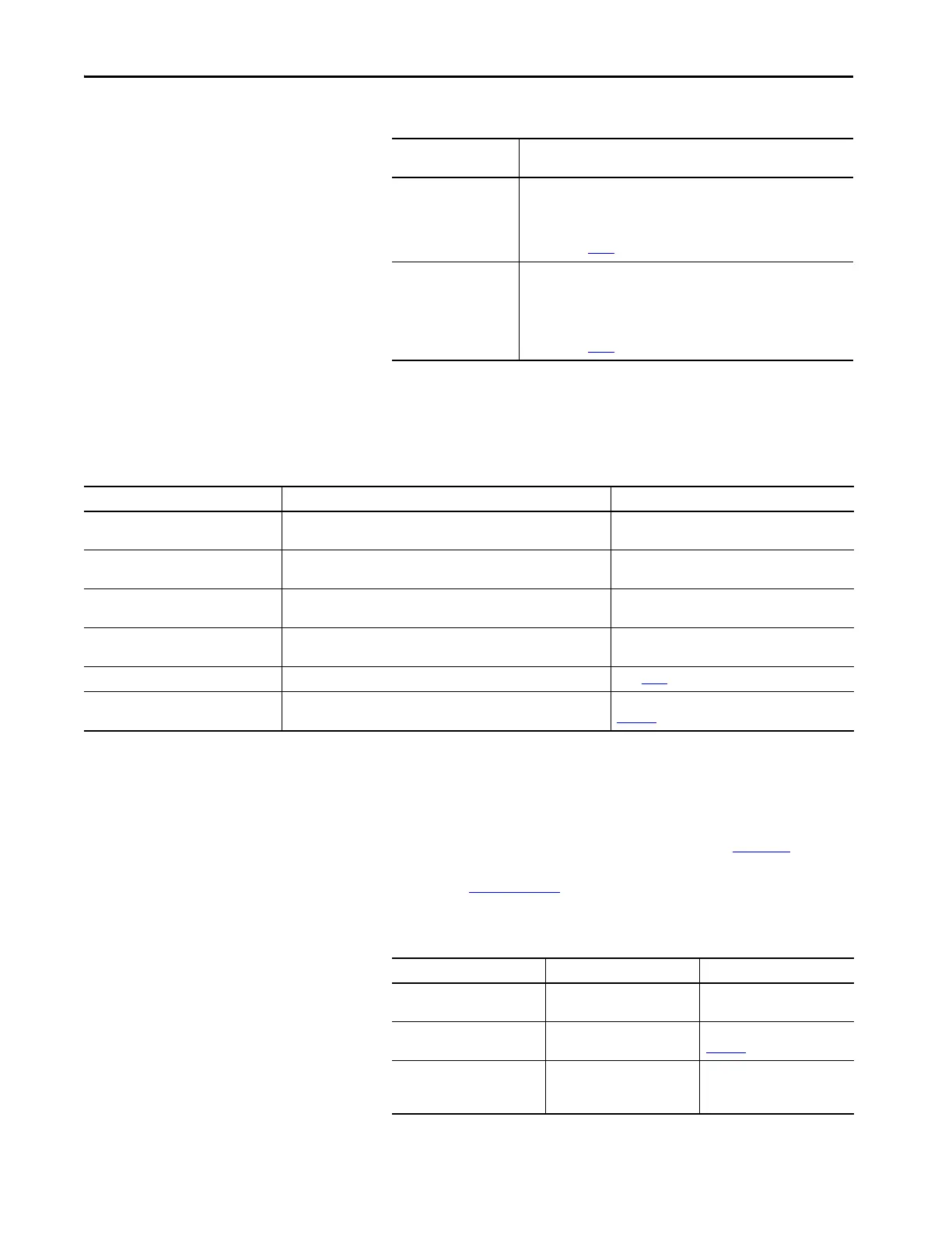
IAM/AM Fault Status Indicator Status Do This
Actively cycling (phase 0)
The drive is looking for a closed Sercos ring. Wait for phase 1 or take
corrective action until you reach phase 1.
Check fiber-optic connections.
Displaying a fixed 1 (phase 1)
The drive is looking for active nodes. Wait for phase 2 or take corrective
action until you reach phase 2.
Check node addressing.
Displaying a fixed 2 (phase 2)
The drive is configuring nodes for communication. Wait for phase 3 or take
corrective action until you reach phase 3.
Check program motor and drive configuration against
installed hardware.
Displaying a fixed 3 (phase 3)
The drive is configuring device specific parameters. Wait for phase 4 or take
corrective action until you reach phase 4.
Check motor catalog number against selection.
(1)
Displaying a fixed 4 (phase 4) The drive is configured and active. Go to step 6.
Flashing an E followed by two numbers Drive is faulted.
Go to Kinetix 6000 Drive System Error Codes on
page 167.
(1) You can get diagnostic information from the module by highlighting the module name in the Logix Designer application. A Pseudo Key Failure often indicates that the motor selection does not match
the motor installed.
Three Sercos Indicators Status Do This
Flashing green and red Establishing communication
Wait for steady green on all three
indicators.
Steady green Communication ready
Go to Test and Tune the Axes on
page 157
.
Not flashing green and red/
not steady green
Sercos module is faulted
Go to the appropriate Logix5000
manual for specific instructions
and troubleshooting.

 Loading...

