Using
Application Specific Instructions
11–5
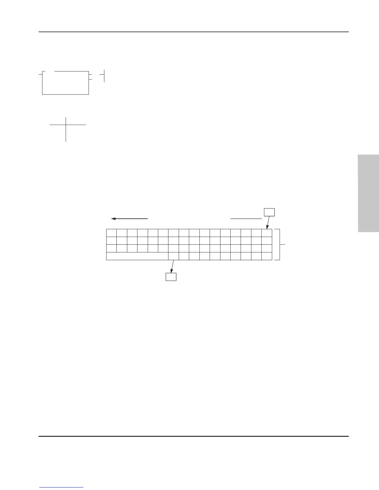
Bit Shift Left (BSL)
When the rung goes from false-to-true, the controller sets the enable bit (EN bit 15)
and the data block is shifted to the left (to a higher bit number) one bit position. The
specified bit at the bit address is shifted into the first bit position. The last bit is
shifted out of the array and stored in the unload bit (UL bit 10). The shift is
completed immediately.
For wraparound operation, set the bit address to the last bit of the array or to the UL
bit.
Operation
The following figure shows the operation of the BSL instruction shown above.
19 18 17 16
35 34 33
51 50 49 48
67 66 65 64
32
23 22 21 20
39 38 37
55 54 53 52
71 70 69 68
36
27 26 25 24
43 42 41
59 58 57 56
73 72
40
31 30 29 28
47 46 45
63 62 61 60
44
RESERVED
58 Bit Array #B3:1
Source Bit
I:0/05
Unload Bit
(R6:03/10)
Data block is shifted one bit at a
time from bit B3/16 to bit B3/73.
If you wish to shift more than one bit per scan, you must create a loop in your
application using the JMP
, LBL, and CTU instructions.
Programming
53.71+
5.24/word
Execution Times
(µsec) when:
False
True
19.80
(EN)
(DN)
BSL
BIT SHIFT LEFT
File
Control
Bit Address
Length
efesotomasyon.com - Allen Bradley,Rockwell,plc,servo,drive

 Loading...


