Preface
MicroLogix 1000 Programmable Controller User Manual
13–8
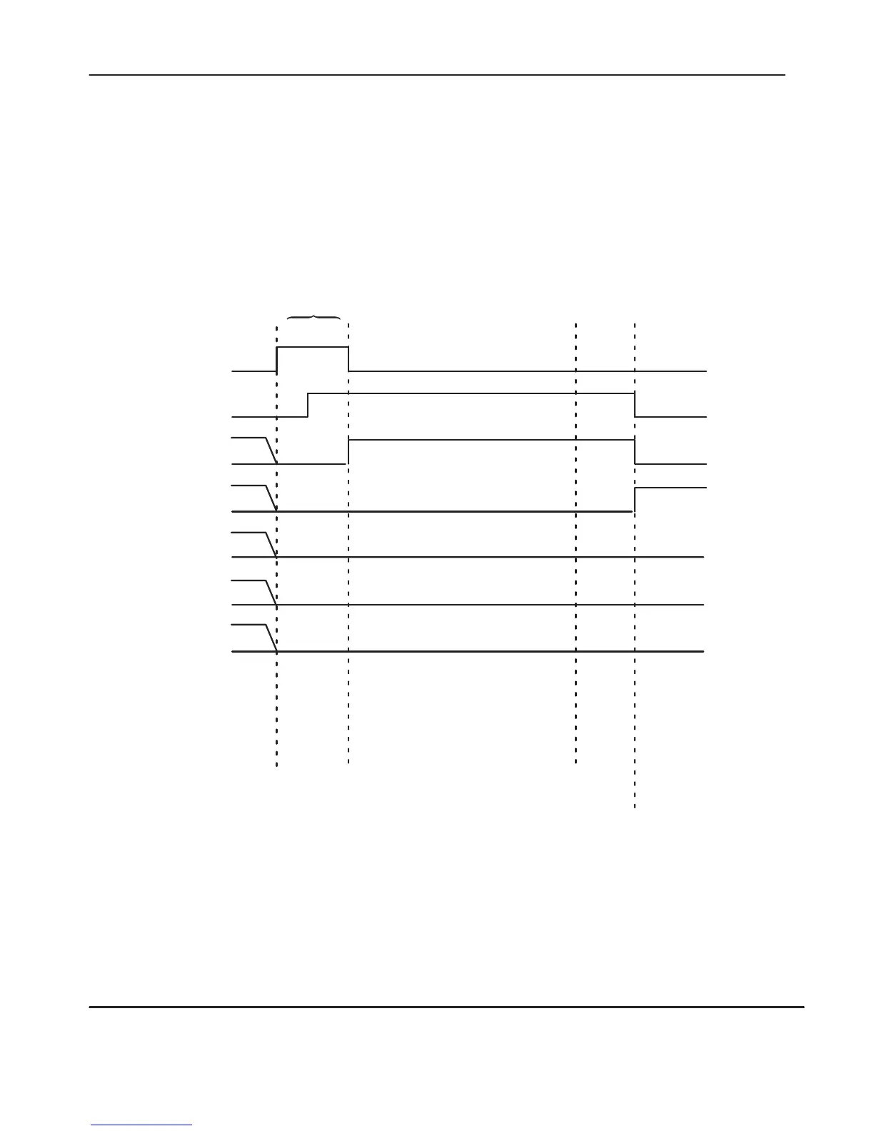
Timing Diagram for a Successful MSG Instruction
The following section illustrates a successful timing diagram for a Series D or later
MicroLogix 1000 discrete controller, or a MicroLogix 1000 analog controller
, MSG
instruction.
Rung goes True.
Target node
receives packet.
Target node processes packet
successfully and returns data
(read) or writes data (success).
Bit 15 EN
Enabled
Bit 10 EW
Enabled
and W
aiting
Bit 14 ST
Start
1
0
1
0
1
0
Bit 13 DN
Done
1
0
Bit 9 NR
Negative
Response
1
0
Bit 8 TO
Time
Out
1
0
Target node
sent reply.
Control Block Status Bits
Bit 12 ER
Error
1
0
The EW bit is set (1) and the
ST
, DN, NR, and
TO flags are cleared. If the
transmit buffer is not available, the EN flag remains false (0).
When rung conditions go true and the transmit buffer becomes available, the
EN flag goes true (1). The EN bit remains set until either the DN, ER, or TO
bit is set. The
TO bit has no ef
fect unless the ST bit has first been set.
efesotomasyon.com - Allen Bradley,Rockwell,plc,servo,drive

 Loading...


