Preface
MicroLogix 1000 Programmable Controllers User Manual
2–2
Grounding Guidelines
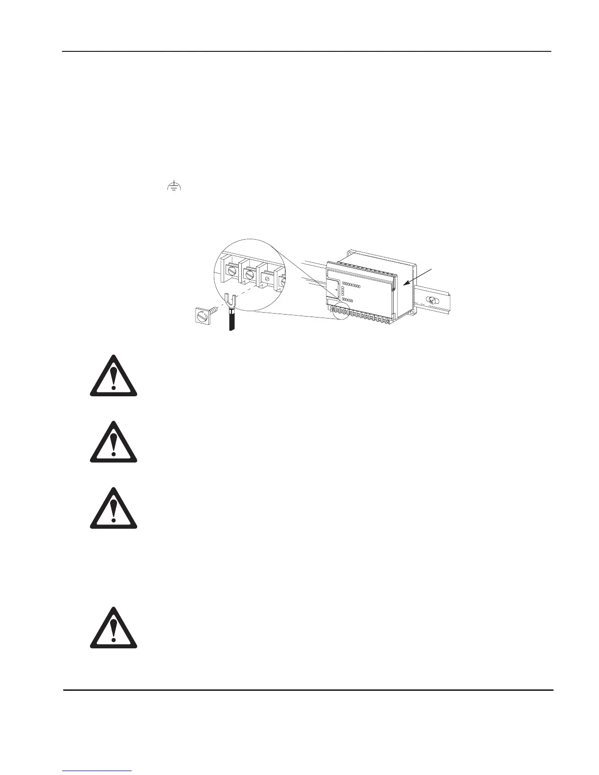
In solid-state control systems, grounding helps limit the effects of noise due to
electromagnetic interference (EMI). Use the heaviest wire gauge listed for wiring
your controller with a maximum length of 152.4 mm (6 in.). Run the ground
connection from the ground screw of the controller (third screw from left on output
terminal rung) to the ground bus.
Note
This symbol denotes a functional earth ground terminal which pr
ovides a low
impedance path between electrical cir
cuits and earth for
non-safety
purposes, such
as noise immunity impr
ovement.
Protective
Wrap (remove after wiring)
All devices that connect to the user 24V power supply or to the RS-232 channel
must be refer
enced to chassis gr
ound or floating. Failure to follow this
procedure may result in property damage or personal injury.
Chassis gr
ound, user 24V ground, and RS-232 ground are internally
connected. You must connect the chassis ground terminal scr
ew to chassis
ground prior to connecting any devices.
On the 1761-L10BWB, 1761-L16BWB, 1761-L16BBB, 1761-L20BWB-5A,
1761-L32BBB, and 1761-L32BWB controllers, the user supply 24 V dc IN and
chassis gr
ound are internally connected.
You must also provide an acceptable grounding path for each device in your
application. For more information on proper grounding guidelines, see the
Industrial Automation W
iring and Gr
ounding Guidelines
publication 1770-4.1.
Remove the protective wrap before applying power to the controller. Failure
to remove the wrap may cause the controller to overheat.
efesotomasyon.com - Allen Bradley,Rockwell,plc,servo,drive

 Loading...


