Preface
MicroLogix 1000 Programmable Controllers User Manual
1–8
Using Surge Suppressors
Inductive
load devices such as motor starters and solenoids require the use of some
type of surge suppression to protect the controller output contacts. Switching
inductive loads without sur
ge suppression can
significantly reduce the lifetime of
relay contacts. By adding a suppression device directly across the coil of an
inductive device, you will prolong the life of the switch contacts. Y
ou will also
reduce the effects of voltage transients caused by interrupting the current to that
inductive device, and will prevent electrical noise from radiating into system wiring.
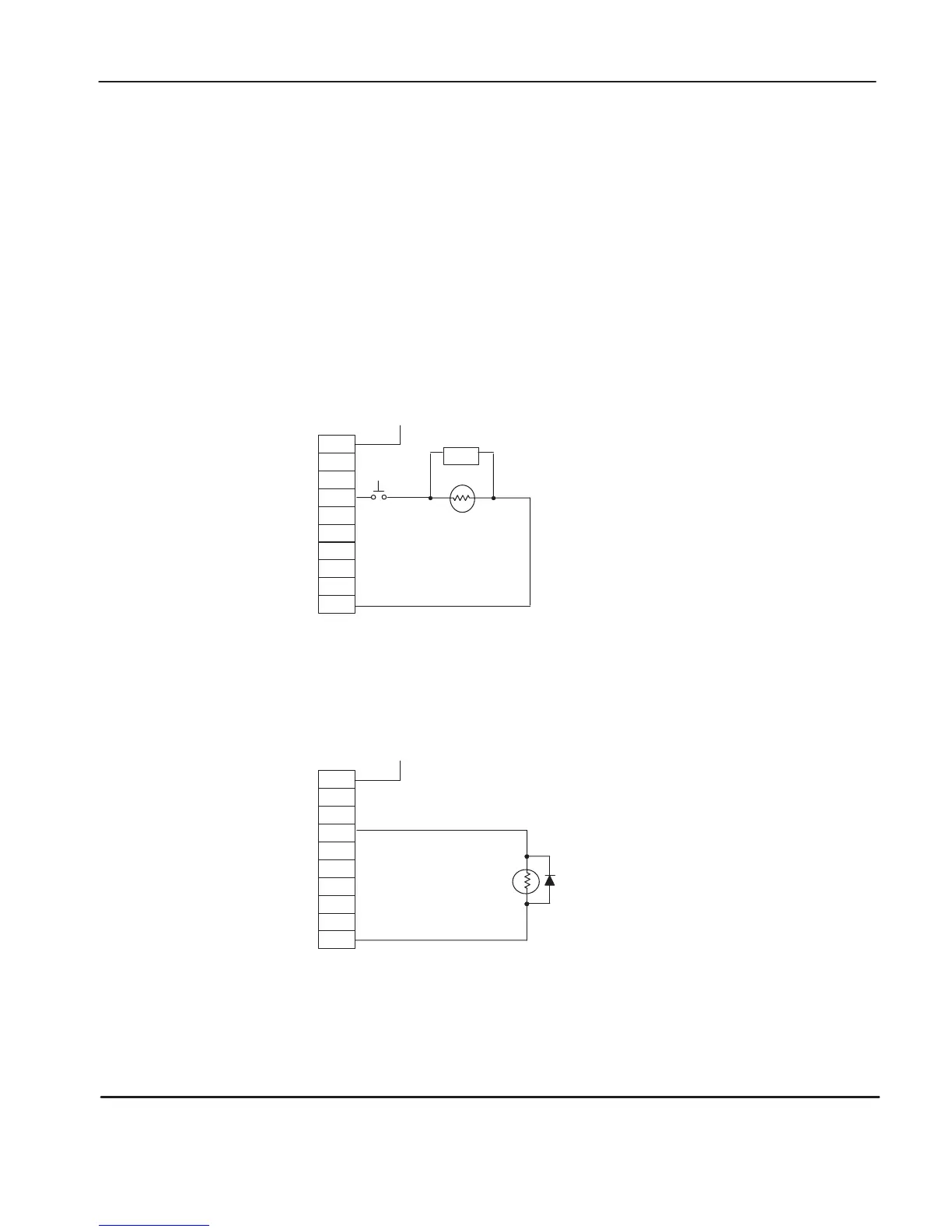
The following diagram shows an output with a suppression device. We recommend
that you locate the suppression device as close as possible to the load device.
OUT
1
OUT 5
OUT 6
OUT 7
OUT 2
VAC/VDC
OUT 0
OUT 3
COM
+
dc or L1
OUT
4
Snubber
ac
or dc
Outputs
dc COM or L2
If you connect a micro controller FET output to an inductive load, we recommend
that you use an 1N4004 diode for sur
ge suppression, as shown in the illustration that
follows.
OUT
1
OUT 5
OUT 6
OUT 7
OUT 2
VAC/VDC
OUT 0
OUT 3
COM
+24V
dc
OUT
4
Relay
or Solid State
dc Outputs
24V dc common
IN4004 Diode
efesotomasyon.com - Allen Bradley,Rockwell,plc,servo,drive

 Loading...


