Preface
MicroLogix 1000 Programmable Controllers User Manual
1–16
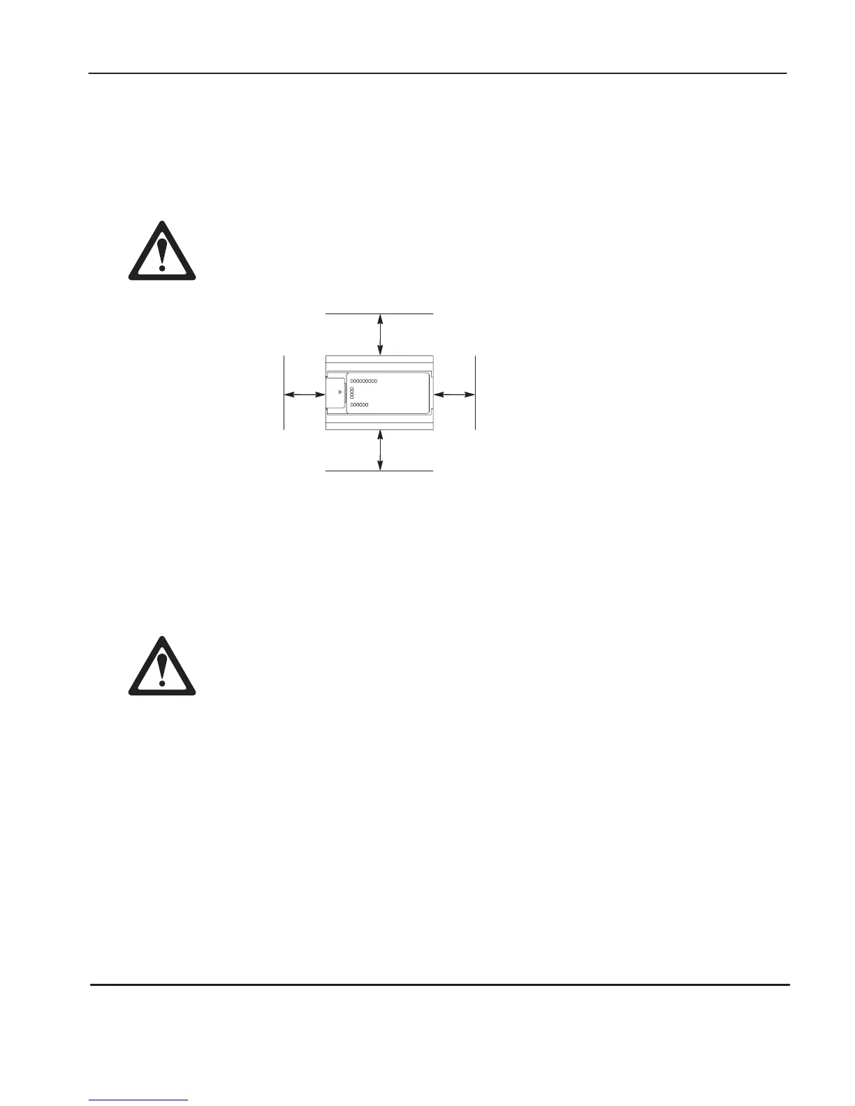
Controller Spacing
The following figure shows the recommended minimum spacing for the controller.
(Refer to appendix A for controller dimensions.)
Explosion Hazard — For Class I, Division 2 applications, this product must be
installed in an enclosure. All cables connected to the product must remain in
the enclosur
e or be pr
otected by conduit or other means.
20142
B
A
A. Greater than or equal to 50.8 mm (2 in.).
B. Greater than or equal to 50.8 mm (2 in.).
B
A
Top
Bottom
SideSide
Mounting the Controller
This
equipment is suitable for Class I, Division 2, Groups A, B, C, D or
non-hazardous locations only, when product or packaging is marked.
Explosion Hazard:
• Substitution of components may impair suitability for Class I, Division 2.
•
Be car
eful of metal chips when drilling mounting holes for your controller.
Drilled fragments that fall into the controller could cause damage. Do not
drill holes above a mounted controller if the protective wrap is removed.
The controller should be mounted horizontally within an enclosure, using a DIN rail
or mounting screws.
efesotomasyon.com - Allen Bradley,Rockwell,plc,servo,drive

 Loading...


