Preface
MicroLogix 1000 Programmable Controllers User Manual
2–22
Wiring
Y
our Analog Channels
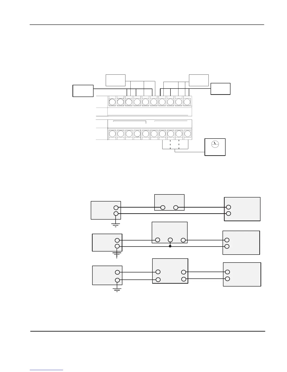
Analog input circuits can monitor current and voltage signals and convert
them to serial digital data. The analog output can support either a voltage or
a current function.
VAC
VDC
O/4 O/5 O/6
NOT
USED
O/7
I/10 I/11
IA
(–)
IA/3
I
(+)
IA/2
I (+)
IA
SHD
IA/1
V (+)
IA
SHD
IA/0
V (+)
IA
(–)
OA
(–)
OA/0
I (+)
OA/0
V (+)
OA
SHD
– OR –
Jumper
unused
inputs.
Sensor 1
Sensor 2
Sensor 3
Sensor 4
meter
(V)
V
oltage
(V) V
oltage
(I) Current
(I) Current
You can configure either voltage
or current output operation.
For increased noise immunity, connect a ground wire directly from the
shield terminals to chassis ground.
2-Wire Transmitter
Transmitter
+–
4-Wire Transmitter
Transmitter
Supply Signal
+
–
+
–
IA/0 – 3 (+)
IA (–)
Controller
IA/0 – 3 (+)
IA (–)
Controller
+Power
Supply
–
+
Power
Supply
–
Important: The controller does not provide loop power for analog inputs.
Use a power supply that matches the transmitter specifications.
3-Wire Transmitter
Transmitter
Supply Signal
GND
IA/0 – 3 (+)
IA (–)
Controller
+
Power
Supply
–
efesotomasyon.com - Allen Bradley,Rockwell,plc,servo,drive

 Loading...


