Preface
MicroLogix 1000 Programmable Controllers User Manual
2–4
NOT
USED
NOT
USED
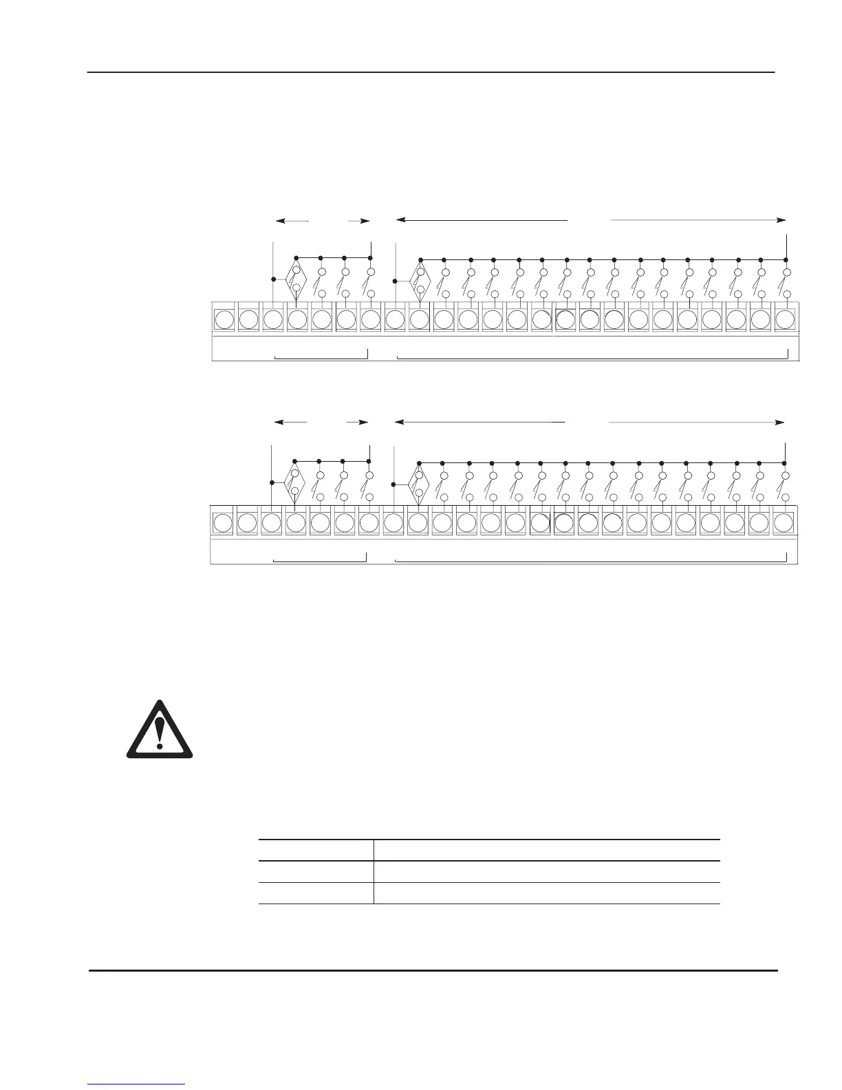
I/9 I/10
DC
COM
I/0 I/1 I/2 I/3 I/4 I/5 I/6 I/7 I/8 I/11 I/12 I/13 I/14 I/15 I/16 I/17 I/18
DC
COM
I/19
VDC
(+) for Sinking
14–30 VDC
VDC (–) for Sourcing
VDC (+) for Sourcing
14–30 VDC
VDC (–) for Sinking
NOT
USED
NOT
USED
I/9 I/10
DC
COM
I/0 I/1 I/2 I/3 I/4 I/5 I/6 I/7 I/8 I/11 I/12 I/13 I/14 I/15 I/16 I/17 I/18
DC
COM
I/19
VDC (–) for Sourcing
14–30 VDC
14–30 VDC
VDC (+) for Sinking
VDC (–) for Sinking
VDC (+) for Sourcing
Sinking
Inputs
Sourcing Inputs
Sinking Inputs
Sourcing Inputs
1761-L32BWB, -L32BBB (Wiring Diagrams also apply to 1761-L20BWB-5A,
-L16BWB, -L10BWB, -L16BBB.)
Wiring Recommendations
Before you install and wire any device, disconnect power to the controller
system.
The following are general recommendations for wiring your controller system.
• Each wire terminal accepts 2 wires of the size listed below:
Wire Type Wire Size (2 wire maximum per terminal screw)
Solid #14 to #22 AWG
Stranded #16 to #22 AWG
Refer to page 2–24 for wiring your high-speed counter.
efesotomasyon.com - Allen Bradley,Rockwell,plc,servo,drive

 Loading...


