Preface
MicroLogix 1000 Programmable Controllers User Manual
14–2
Understanding the Controller LED Status
Between the time you apply power to the controller and the time it has to establish
communication with a connected programming device, the only form of
communication between you and the controller is through the LEDs.
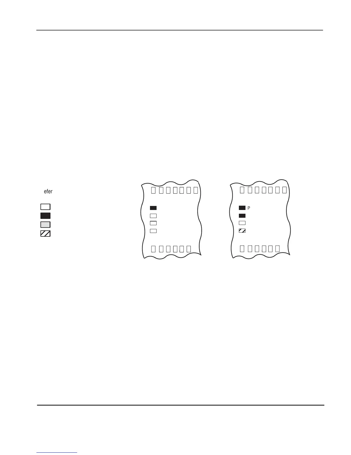
When Operating Normally
When power is applied, only the power LED turns on and remains on. This is part
of the normal powerup sequence.
When the controller is placed in REM Run mode, the run LED also turns on and
remains on, as shown on the right in the figure below. If a force exists, the force
LED is on as well.
When powered up:
FAULT
FORCE
POWER
RUN
When placed in RRUN:
FAULT
FORCE
POWER
RUN
Refer to the following key to determine
the status of the LED indicators:
Indicates the LED is OFF.
Indicates the LED is ON.
Indicates the LED is FLASHING.
Status of LED does not matter.
efesotomasyon.com - Allen Bradley,Rockwell,plc,servo,drive

 Loading...


