EasyManua.ls Logo

Allen-Bradley PLC-5 User Manual

Allen-Bradley PLC-5
388 pages
To Next Page IconTo Next Page
To Previous Page IconTo Previous Page
Page #268 background image
Publication 1785-UM012D-EN-P - July 2005
18-6 Using Processor Input Interrupts
Monitoring Controller
Input Interrupts
Use the controller status screen in your programming software to monitor
PIIs.
Use S:51/0-15 within the PII file because these bits are:
mapped from the actual input module being used for the PII
retentive
For the PII routine to execute properly, do not use the addresses of the input
module’s bits within the PII routine.
This PII Field Stores
Status File
Address
Events since last
interrupt
Displays the number of PII events (the input conditions that caused the interrupt)
since the last interrupt.
S:52
PII changed bits Displays the bit transitions that caused the interrupt. You can use this information
to condition other rungs in your ladder program.
If one of these bits is already set (i.e., a previous interrupt set the bit), the controller
sets a minor fault (S:10/2) to indicate a possible PII overlap. If you want to monitor
this overlap, make sure the last rung in your PII program clears this return mask in
the status file.
S:51
Last scan time Displays the current or last scan time through the PII.
S:55
Max observed scan
time
Displays the maximum value that was displayed in the last
scan field.
S:56
Word not in local
rack
This box is checked if the input word number specified is not on the local rack or if
there is not an input module in the slot addressed.
S:10/11
No command blocks This box is checked if no command blocks exist to get the PII. You can use the
controller’s internal counter or bit transition to execute the PII.
S:10/13
User routine overlap This box is checked if a set condition exists in the PII return mask or changed bits
(possibly set by a previous interrupt) before completing the currently executing PII
routine. PII changed bits are retentive. It may be necessary to place a MOV
instruction on the last rung in the PII file. Move 0 in S:51 to reset the PII bits before
finishing the PII file. If this is not done, a PII overlap bit will be set on that status
page, causing this minor fault.
S:10/12

Table of Contents

Other manuals for Allen-Bradley PLC-5

Question and Answer IconNeed help?

Do you have a question about the Allen-Bradley PLC-5 and is the answer not in the manual?

Allen-Bradley PLC-5 Specifications

General IconGeneral
Programming SoftwareRSLogix 5
Programming LanguagesLadder Logic
Power Supply120/240V AC or 24V DC
Communication PortsDH+, Remote I/O, Ethernet/IP, ControlNet
Operating Temperature0 to 60°C (32 to 140°F)
Relative Humidity5 to 95% non-condensing
MemoryUp to 64K words (user program and data)

Summary

Preface

Manual Overview

Outlines the manual's three main sections: Design, Operate, and Maintain.

Chapter 1 Understanding Your Programmable Controller

Lay Out the System

Guides on determining network configuration and component placement for PLC-5 systems.

Programming Features

Highlights the programming features of a PLC-5 controller, including ladder logic and SFCs.

Chapter 2 Selecting and Placing I/O

Selecting I/O Modules

Guides on selecting I/O modules to interface with machines and processes.

Chapter 3 Placing System Hardware

Determining the Proper Environment

Details acceptable environmental conditions for controller placement.

Grounding Your System

Provides information on proper grounding guidelines for system hardware.

Chapter 4 Addressing I/O and Controller Memory

I/O Addressing Concept

Explains how controller memory segments are used to address I/O terminals.

Assigning Racks

Details how chassis size and addressing mode determine the number of I/O racks.

Chapter 6 Communicating with Remote I/O

Designing a Remote I/O Link

Outlines steps and guidelines for designing a remote I/O link.

Chapter 8 Communicating with Extended-Local I/O

Configuring the Controller as an Extended-Local I/O Scanner

Guides on configuring channel 2 for extended-local I/O as a scanner.

Chapter 10 Communicating with Devices on a Serial Link

Configuring Channel 0

Explains how to configure channel 0 for DF1 point-to-point, master, slave, or user mode.

Chapter 11 Communicating with Devices on an Ethernet Network

Configuring Channel 2 for Ethernet Communication

Guides on configuring channel 2 for Ethernet communication using manual or BOOTP methods.

Using Advanced Ethernet Functions

Explains advanced functions like broadcast address, subnet masks, and gateways.

Chapter 12 Protecting Your Programs

Passwords and Privileges

Explains how passwords and privileges restrict access to controller files and functions.

Chapter 13 Programming Considerations

Forcing

Explains how to turn input/output bits on/off for testing purposes.

Extended Forcing

Describes how to force discrete I/O, analog I/O, and block-transfer data words.

Chapter 15 Preparing Fault Routines

Understanding the Fault Routine Concept

Explains how fault routines execute when a major fault is encountered.

Monitoring Faults

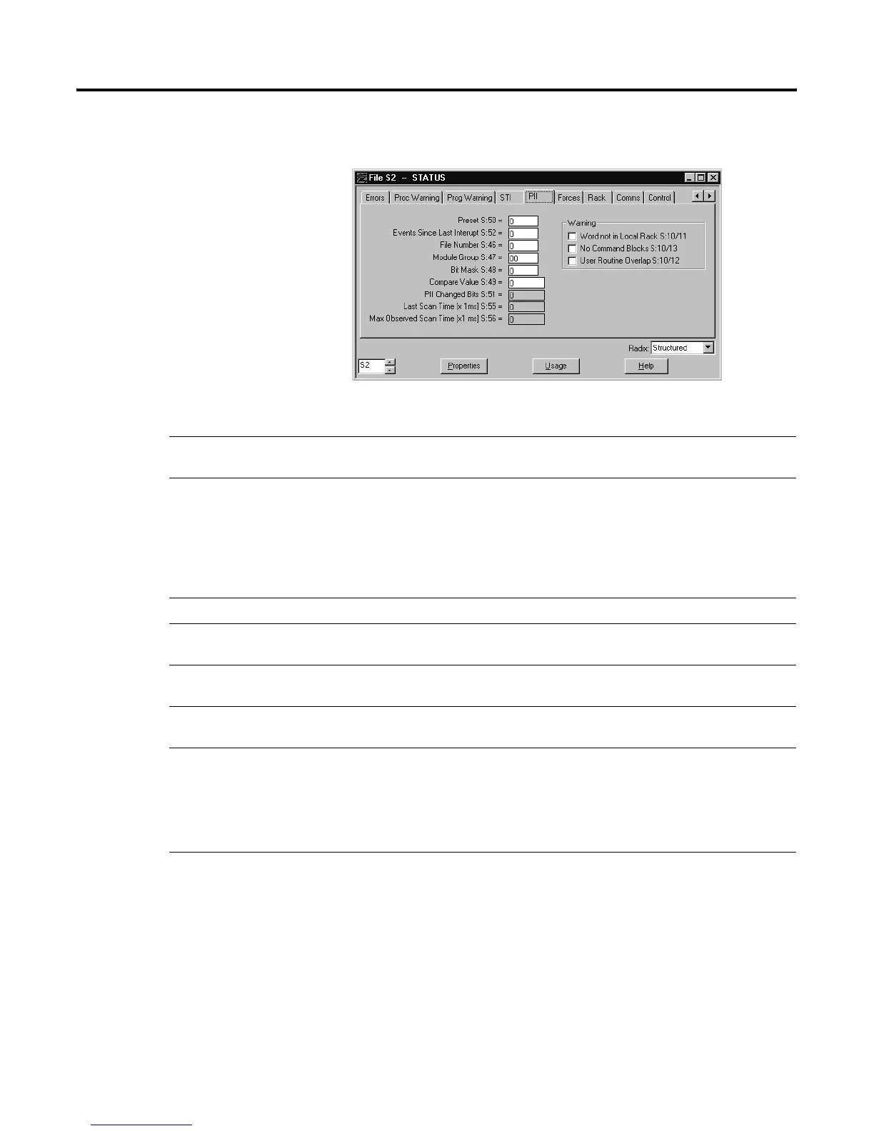
Describes how to monitor controller faults using the status screen.

Appendix F Troubleshooting

PLC-5 controller

Lists general problems for PLC-5 controllers, probable causes, and recommended actions.

Extended-Local I/O system

Offers troubleshooting guidance for the 1771-ALX adapter module.

Appendix G Cable Reference

Channel 0 Pin Assignments

Shows pin assignments for channel 0 (RS-port) for different serial communication modes.

Ethernet Cable Connections

Describes Ethernet cable connections and transceiver specifications.

Related product manuals