Publication 1785-UM012D-EN-P - July 2005
3-6 Placing System Hardware
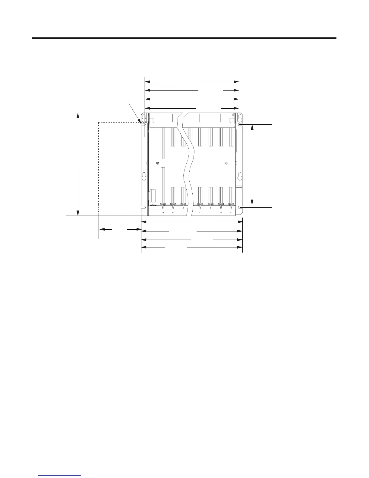
I/O Chassis and External Power Supply Dimensions
Grounding Your System
For more information on proper grounding guidelines, see the Industrial
Automation Wiring and Grounding Guidelines, publication 1770-4.1.
315mm
(12.41")
610mm
(24.01")
16-slot 1771-A4B
483mm
(19.01")
12-slot 1771-A3B1
356mm
(14.01")
229mm
(9.01")
8-slot 1771-A2B
4-slot 1771-A1B
254mm
(10")
12-slot
8-slot
4-slot
16-slot
External
Power
Supply
Use .25"dia
mounting bolts
(4 places)
12451-I
91mm
(3.6")
591mm
(23.25")
464mm
(18.25")
337mm
(13.25")
210mm
(8.25")
Clearance depth is 204mm (8") for 8 I/O connection points per module.

 Loading...


