Publication 1785-UM012D-EN-P - July 2005
4-16 Addressing I/O and Controller Memory
Addressing
Valid formats for addressing data files are:
For more information about entering addresses, see the documentation for
your programming software.
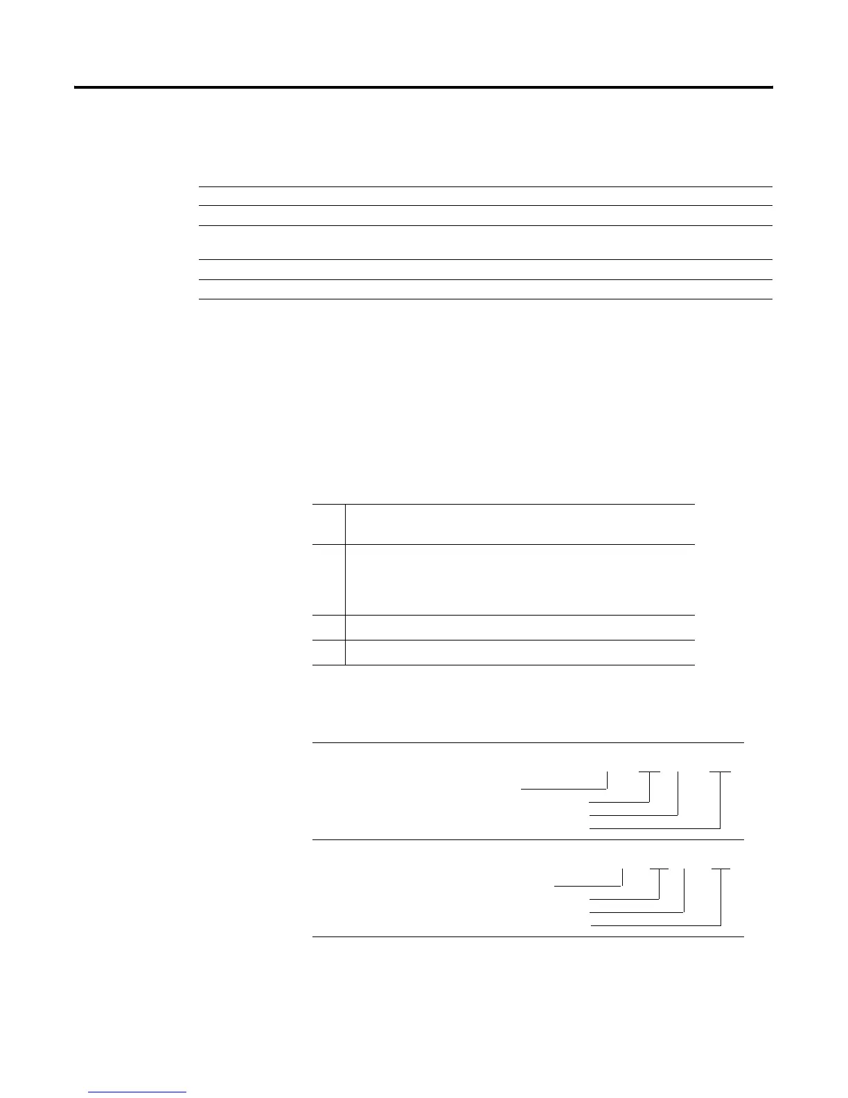
Specifying I/O Image Addresses
The I/O image address corresponds to the physical location of the I/O circuit
in the I/O chassis:
If You Want to Access Use this Addressing Format And See Page
Input or output bit in the I/O image table I/O image address 4-16
Bit, word, sub-member, data block, file, or I/O image bit Logical address 4-17
A component within a logical address by substituting the
value in another address
Indirect address 4-18
An address offset by some number of elements Indexed address 4-20
A substitute name for an address Symbolic address 4-21
a I/O address identifierI = input device
O = output device
bb I/O Rack numberPLC-5/11, -5/20, -5/20E00-03 (octal)
PLC-5/3000-07 (octal)
PLC-5/40, -5/40L, -5/40E00-17 (octal)
PLC-5/60, -5/60L, -5/80, -5/80E00-27 (octal)
c I/O Group number0-7 (octal)
dd Terminal (bit) number00-17 (octal)
To Specify this
Address
Example
Input Image Bit
Output Image Bit
I for input
2-digit I/O rack Number
I/O group number (0-7)
Input number (0-7, 10-17)
I:017/01
O for output
2-digit I/O rack Number
I/O group number (0-7)
Output number (0-7, 10-17)
O:017/01

 Loading...


