1 Publication 1785-UM012D-EN-P - July 2005
Appendix
G
Cable Reference
Using This Chapter
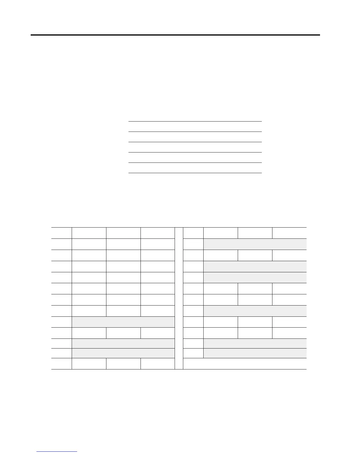
Channel 0 Pin Assignments
The side label of the controller shows a table listing channel 0 (RS-port) pin
assignments. This table shows the same information:
For Information About Go to Page
Channel 0 pin assignments
G-1
Serial cable pin assignments
G-2
Connecting diagrams
G-3
Programming cable specification
G-5
Ethernet cable connections
G-9
Pin RS-232C RS-422A RS-423 Pin RS-232C RS-422A RS-423
1 C.GND C.GND C.GND 14 NOT USED
TXD.OUT
-
SEND COM
2 TXD.OUT
TXD.OUT
+
TXD.OUT 15
3 RXD.IN
RXD.IN
+
RXD.IN 16 NOT USED
RXD.IN
-
REC COM
4 RTS.OUT
RTS.OUT
+
RTS.OUT 17
5 CTS.IN
CTS.IN
+
CTS.IN 18
6 DSR.IN
DSR.IN
+
DSR.IN 19 NOT USED
RTS.OUT
-
NOT USED
7 SIG.GND SIG.GND SIG.GND 20 DTR.OUT
DTR.OUT
+
DTR.OUT
8 DCD.IN
DCD.IN
+
DCD.IN 21
9 22 NOT USED
DSR.IN
-
NOT USED
10 NOT USED
DCD.IN
-
NOT USED 23 NOT USED
DTR.OUT
-
NOT USED
11 24
12 25
13 NOT USED
CTS.IN
-
NOT USED
The shading indicates that the pin is reserved.

 Loading...


