Publication 1785-UM012D-EN-P - July 2005
5-4 Communicating with Controller-Resident I/O
If your application cannot support this configuration, condition the immediate
I/O instructions with the control bits of the adjacent block-transfer module.
This technique helps make certain that an adjacent block-transfer module is
not performing a block-transfer while an immediate I/O instruction is
executing in its adjacent input module.
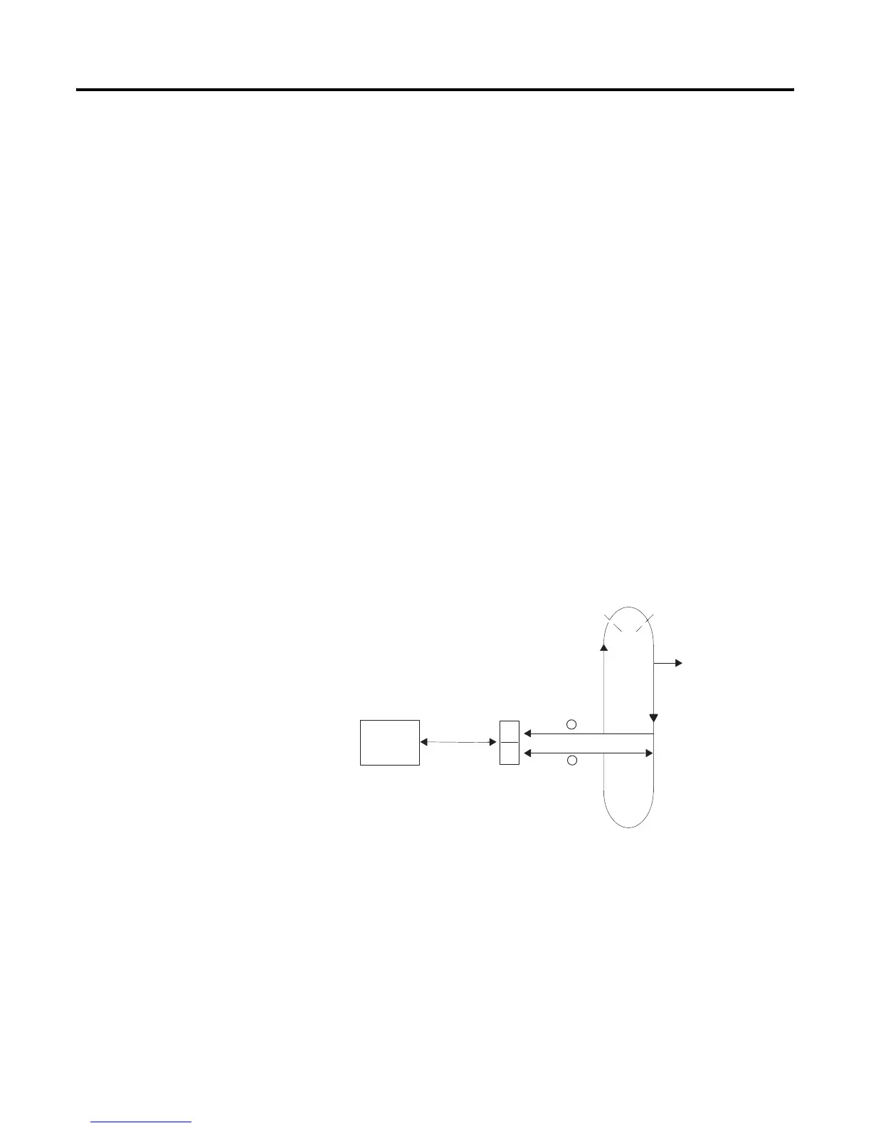
Transferring Block-Transfer Data to Controller-Resident I/O
The controller performs block-transfers at the same time as it scans the
program.
Block-transfers to controller-resident local I/O follow these procedures:
• Block-transfer requests are queued for the addressed controller-resident
local I/O rack.
• The active buffer continuously handles all block-transfer modules
whose block-transfer instructions were enabled in the program scan via
the queue scan in the order the requests were queued.
• Block-transfers of I/O data can finish and the done bit can be set
anytime during the program scan.
The controller runs all enabled block-transfers of I/O data to
controller-resident I/O continuously as each block-transfer request enters the
active buffer.
Configuring the System
for Controller-Resident I/O
To configure the system for controller-resident local I/O, you need to set the
I/O chassis switch to indicate the rack-addressing mode. The addressing mode
determines the number of controller-resident rack numbers used based on the
number of slots in the chassis. For more information on addressing modes, see
chapter 4. To set the I/O chassis switch, see Appendix E.
The controller-resident rack address defaults to rack 0. If needed, you can set it
for rack 1 by setting user control bit 2 (S26:2) on the controller configuration
screen in your programming software. If you select rack 1 as the
controller-resident rack, rack 0 becomes unavailable for your system.
Controller-
Rack 0
Resident
Housekeeping
Program
Scan
Interrupt
from STI or
Fault Routine
BTR or BTW Data
Multiple
Block Transfers
Q
A
Q = queue
A = active buffer (block-transfer
data buffered here)
1
2

 Loading...


