Publication 1785-UM012D-EN-P - July 2005
Maximizing System Performance C-11
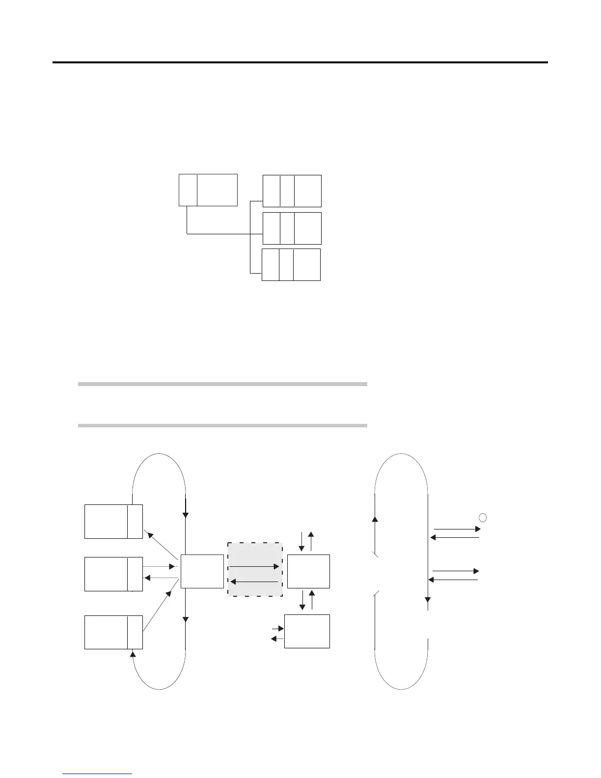
To optimize your system layout for block-data transfers, use an arrangement
similar to the following:
Controller Time
The controller time is the time needed to process the inputs and set the
corresponding outputs. This controller time varies for different controllers
and is based on input buffering, program scan, etc.
PLC
Adapter
BT
BT
Adapter
Adapter
With this arrangement, a block-transfer to each BT
module can occur in a single discrete I/O scan.
Maximum scan time
Minimum time to complete
a block-transfer to all modules
= 3 discrete scans + 3 block-transfers
= 3D + 3BT
= 1 (3D + 3BT)
= 3D + 3BT
BT
System Optimized for Block-Data Transfer
In a PLC-5 system, inputs are buffered between the I/O image table and the remote I/O
buffer. The movement of inputs from the remote I/O buffer to the input buffer is
asynchronous to the movement of data from the input buffer to the input image table.
ab
AdapterAdapter Adapter
IOT (x)
IIN (y)
x
y
Rack 3
Rack 2
Rack 1
Housekeeping
Scan
Logic
Processor-
Resident
Rack
Data
Exchange
Immediate I/O
Data Exchange
I/O Image
Table
Remote I/O
Buffer
Program Scan LoopRemote I/O Scan Loop
Update
I/O image
from input
buffer
a
write outputs
b
read inputs
Input
Buffer
1

 Loading...


