EasyManua.ls Logo

Allen-Bradley PLC-5 User Manual

Allen-Bradley PLC-5
388 pages
To Next Page IconTo Next Page
To Previous Page IconTo Previous Page
Page #330 background imageLoading...
Page #330 background image
Publication 1785-UM012D-EN-P - July 2005
D-30 Instruction Set Quick Reference
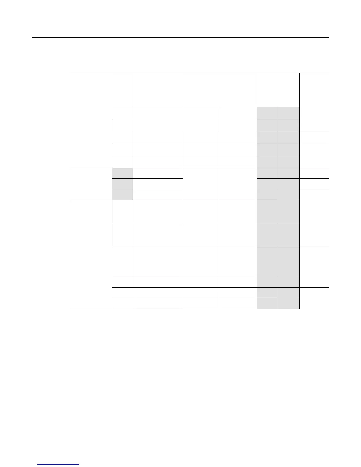
Bit and Word Instructions
Category Code Title Execution Time (µs) Integer Execution Time
(µs)
Floating Point
Words of
Memory
(1)
True False True False
Relay XIC examine if closed .32 .16
1
(2)
XIO examine if open .32 .16
1
2
OTL output latch .48 .16
1
2
OTU output unlatch .48 .16
1
2
OTE output energize .48 .48
1
2
Branch branch end .16 .16 1
next branch 1
branch start 1
Timer and Counter TON timer on(0.01 base)
(1.0 base)
3.8
4.1
2.6
2.5
2-3
TOF timer off(0.01 base)
(1.0 base)
2.6
2.6
3.2
3.2
2-3
RTO retentive timer on
(0.01 base)
(1.0 base)
3.8
4.1
2.4
2.3
2-3
CTU count up 3.4 3.4 2-3
CTD count down 3.3 3.4 2-3
RES reset 2.2 1.0 2-3
(1)
Use the larger number for addresses beyond 2048 words in the controllers data table.
(2)
For every bit address above the first 256 words of memory in the data table, add 0.16 µs and 1 word of memory.

Table of Contents

Other manuals for Allen-Bradley PLC-5

Question and Answer IconNeed help?

Do you have a question about the Allen-Bradley PLC-5 and is the answer not in the manual?

Allen-Bradley PLC-5 Specifications

General IconGeneral
Programming SoftwareRSLogix 5
Programming LanguagesLadder Logic
Power Supply120/240V AC or 24V DC
Communication PortsDH+, Remote I/O, Ethernet/IP, ControlNet
Operating Temperature0 to 60°C (32 to 140°F)
Relative Humidity5 to 95% non-condensing
MemoryUp to 64K words (user program and data)

Summary

Preface

Manual Overview

Outlines the manual's three main sections: Design, Operate, and Maintain.

Chapter 1 Understanding Your Programmable Controller

Lay Out the System

Guides on determining network configuration and component placement for PLC-5 systems.

Programming Features

Highlights the programming features of a PLC-5 controller, including ladder logic and SFCs.

Chapter 2 Selecting and Placing I/O

Selecting I/O Modules

Guides on selecting I/O modules to interface with machines and processes.

Chapter 3 Placing System Hardware

Determining the Proper Environment

Details acceptable environmental conditions for controller placement.

Grounding Your System

Provides information on proper grounding guidelines for system hardware.

Chapter 4 Addressing I/O and Controller Memory

I/O Addressing Concept

Explains how controller memory segments are used to address I/O terminals.

Assigning Racks

Details how chassis size and addressing mode determine the number of I/O racks.

Chapter 6 Communicating with Remote I/O

Designing a Remote I/O Link

Outlines steps and guidelines for designing a remote I/O link.

Chapter 8 Communicating with Extended-Local I/O

Configuring the Controller as an Extended-Local I/O Scanner

Guides on configuring channel 2 for extended-local I/O as a scanner.

Chapter 10 Communicating with Devices on a Serial Link

Configuring Channel 0

Explains how to configure channel 0 for DF1 point-to-point, master, slave, or user mode.

Chapter 11 Communicating with Devices on an Ethernet Network

Configuring Channel 2 for Ethernet Communication

Guides on configuring channel 2 for Ethernet communication using manual or BOOTP methods.

Using Advanced Ethernet Functions

Explains advanced functions like broadcast address, subnet masks, and gateways.

Chapter 12 Protecting Your Programs

Passwords and Privileges

Explains how passwords and privileges restrict access to controller files and functions.

Chapter 13 Programming Considerations

Forcing

Explains how to turn input/output bits on/off for testing purposes.

Extended Forcing

Describes how to force discrete I/O, analog I/O, and block-transfer data words.

Chapter 15 Preparing Fault Routines

Understanding the Fault Routine Concept

Explains how fault routines execute when a major fault is encountered.

Monitoring Faults

Describes how to monitor controller faults using the status screen.

Appendix F Troubleshooting

PLC-5 controller

Lists general problems for PLC-5 controllers, probable causes, and recommended actions.

Extended-Local I/O system

Offers troubleshooting guidance for the 1771-ALX adapter module.

Appendix G Cable Reference

Channel 0 Pin Assignments

Shows pin assignments for channel 0 (RS-port) for different serial communication modes.

Ethernet Cable Connections

Describes Ethernet cable connections and transceiver specifications.

Related product manuals