Publication 1785-UM012D-EN-P - July 2005
4-6 Addressing I/O and Controller Memory
When planning your system design, consider the densities of the I/O modules
you are using and choose an addressing mode that most efficiently uses
controller memory.
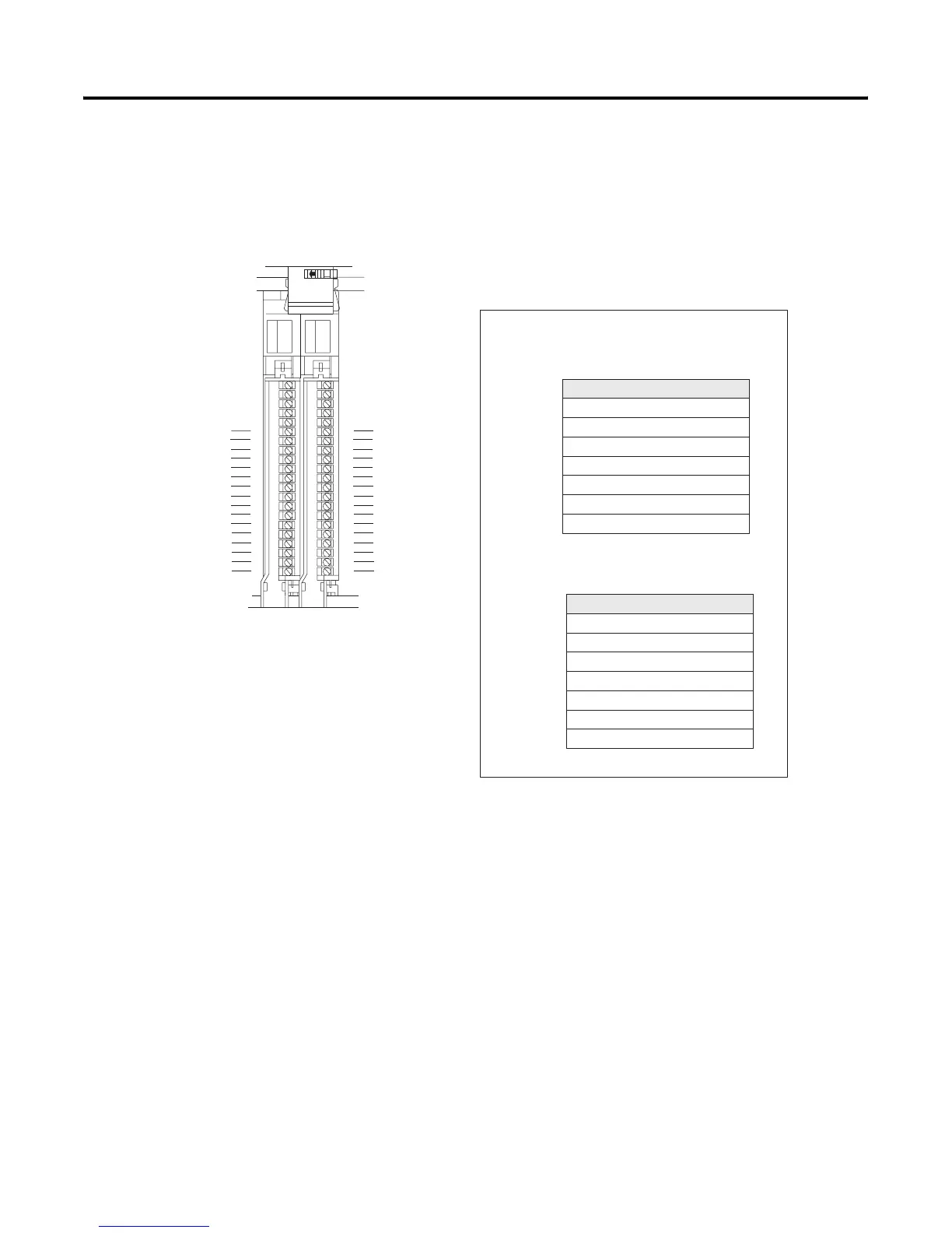
Example of Efficient I/O Image Table Use.
Define the addressing mode for each I/O chassis by setting the chassis
backplane switch assembly. For more information, see Appendix E.
2-slot addressing (2 I/O chassis slot = 1 I/O group = 1 input image
word and 1 output image word = 16 input bits and 16 output bits.)
0
1
2
3
4
5
6
7
Output Image Table
Word #
0
1
2
3
4
5
6
7
Input Image Table
Word #
Controller memory
Rack x
0017 bits
0017 bits
Group 0
16-point I/O modules occupy 16 bits, an entire word, in
the image table.
Installing as a pair a 16-point input module and a
16-point output module efficiently uses the image table.
00
01
02
03
04
05
06
07
10
11
12
13
14
15
16
17
00
01
02
03
04
05
06
07
10
11
12
13
14
15
16
17
Input
Terminals
Output
Terminals

 Loading...


