
Do you have a question about the Allen-Bradley PowerFlex 755 and is the answer not in the manual?
| Category | AC Drive |
|---|---|
| Amperage | 2.2…1470 A |
| Output Voltage | 0 to Input Voltage |
| Output Current | 2.2…1470 A |
| Enclosure | IP20, IP30, IP54 |
| Communications | EtherNet/IP, ControlNet, DeviceNet |
| I/O | Digital, Analog, Encoder, Relay |
| Safety | Safe Speed Monitor |
| Protection Features | Overcurrent, Overvoltage, Undervoltage, Overload, Short Circuit, Ground Fault, Overtemperature |
| Operating Temperature | -10°C to 50°C (14°F to 122°F) |
| Storage Temperature | -40°C to 70°C (-40°F to 158°F) |
| Humidity | 5…95% noncondensing |
| Altitude | Up to 1000m (3300ft) without derating |
| Voltage | 200-240V AC, 380-480V AC, 500-600V AC, 690V AC |
| Input Voltage | 200-240V AC, 380-480V AC, 500-600V AC, 690V AC |
| Control Method | Sensorless Vector |
Overview of Logix controllers, EtherNet/IP network requirements, and necessary software for integrated motion.
Details on controller types and minimum Studio 5000 Logix Designer versions for motion and safety applications.
Lists required software versions for Studio 5000 Logix Designer and RSLinx Classic for integrated motion systems.
Details the EtherNet/IP drives available for integrated motion control applications.
Outlines the two main approaches to setting up an integrated motion solution: connecting hardware first or configuring software first.
Guides users on using Motion Analyzer to select appropriate drives and motors based on application requirements.
Step-by-step instructions for creating a new project in Logix Designer application for motion control.
Explains the importance and configuration of CIP Sync for time synchronization in distributed motion control applications.
Provides instructions on how to add an Ethernet communication module to a Logix Designer project if needed.
Instructions for adding Kinetix 350, 5500, or 6500 EtherNet/IP drives to a Logix Designer project.
Details on configuring the safety category for Kinetix 5500 drives with integrated safety connections.
Guides users on setting power options, bus regulator action, and shunt resistor type in Logix Designer.
Explains how to enter digital input values for Kinetix 5500 and 6500 drives in Logix Designer.
Describes the process of creating an axis and associating it with a Kinetix drive within the project.
Instructions for creating a motion group to organize and manage motion axes within the Logix controller.
Details on configuring the Base Update Period (RPI) for Ethernet communication between controller and motion module.
Guides on configuring axis properties using dialog boxes, adapting to feedback configuration choices.
Explains how to configure associated axis properties and determine the control mode based on attributes.
Details on selecting the origin of motor configuration values: database, nameplate, or nonvolatile memory.
Describes how the Motor Model category displays information based on motor type and data source.
Explains how to select and configure motor feedback devices based on general dialog box settings.
Details how to configure load feedback information from devices coupled to the load-side of mechanical transmission.
Guides on configuring master feedback when the General category is set to Master Feedback.
Instructions for creating external encoder modules and configuring feedback-only axis properties.
Instructions for adding a Kinetix 5700 EtherNet/IP drive, including DC-bus power supply configuration.
Steps to configure the DC-bus power supply and associate an axis with the Kinetix 5700 drive.
Instructions for configuring the regenerative bus supply for Kinetix 5700 drives, including selecting the correct supply.
Details on defining feedback options for each axis after establishing Kinetix 5700 inverters in Logix Designer.
Procedure for configuring Kinetix 5700 inverter drives, including single-axis and dual-axis types.
Guides on selecting safety application mode, connection mode, and power structure for module definition.
Steps to configure power options and safety settings for Kinetix 5700 drives in Logix Designer.
Explains how to configure digital inputs for Kinetix 5700 drives, including selecting input functions and descriptions.
Details on defining feedback options for each axis and establishing feedback port assignments for Kinetix 5700 drives.
Instructions for creating a motion group to manage Kinetix 5700 axes, ensuring proper configuration.
Guides on setting the Base Update Period (RPI) for Ethernet communication for Kinetix 5700 drives.
Details on configuring axis properties for Kinetix 5700 drives, including general, motor, and feedback settings.
Explains how to configure associated axes and determine the control mode for Kinetix 5700 drives.
Guides on selecting the motor data source (Catalog Number, Nameplate, or Motor NV) for Kinetix 5700 drives.
Describes how to display motor model information based on the selected motor type and data source.
Instructions for assigning motor feedback for Kinetix 5700 drives, including selecting feedback type and units.
Details on configuring load feedback information for Kinetix 5700 drives, including device specification.
Guides on configuring master feedback for Kinetix 5700 drives, ensuring proper information entry.
Step-by-step instructions for adding a PowerFlex 755 drive to a Logix Designer project.
Guides on selecting peripheral feedback devices and assigning ports/channels for PowerFlex 755 drives.
Instructions for selecting an I/O card as a peripheral device on port 7 for PowerFlex 755 drives.
Details on assigning the appropriate power structure for a PowerFlex 755 drive configuration.
Guides on setting bus regulator action, shunt resistor type, and configuring power limits for PowerFlex 755 drives.
Explains how to enter digital input values for PowerFlex 755 drives based on peripheral device configuration.
Step-by-step guide to creating an axis and associating it with a PowerFlex 755 drive in Logix Designer.
Instructions for associating an axis to a PowerFlex 755 drive by manually establishing motor feedback port/channel assignments.
Guides on creating a motion group to organize axes for PowerFlex 755 drive configuration.
Details on configuring the Base Update Period for Ethernet communication and motor feedback for PowerFlex 755 drives.
Instructions on configuring axis properties for PowerFlex 755 drives, including general, motor, and scaling settings.
Explains how to configure associated axes and determine control modes for PowerFlex 755 drives.
Guides on selecting the motor data source (Catalog Number, Nameplate, or Drive NV) for PowerFlex 755 drives.
Instructions for setting network configuration (IP address, gateway, subnet mask) using the drive's LCD display.
Step-by-step guide to adding a PowerFlex 527 drive to a Logix Designer project.
Guides on configuring the drive's safety connection type: hard-wired or integrated safety connections.
Instructions for configuring PowerFlex 527 drives with hard-wired safe torque off (STO) connections.
Details on configuring PowerFlex 527 drives with integrated safety connections using Motion and Safety mode.
Guides on setting PWM frequency, bus regulator action, and shunt resistor type for PowerFlex 527 drives.
Explains how to enter digital input values for PowerFlex 527 drives, including Home and Registration inputs.
Steps to create and configure an axis for a PowerFlex 527 drive after adding it to the project.
Instructions for creating a motion group to organize axes for PowerFlex 527 drive configuration.
Guides on configuring axis properties for PowerFlex 527 drives, covering general, motor, and feedback settings.
Explains how to configure associated axes and determine control modes for PowerFlex 527 drives.
Explains how Axis Scheduling improves controller performance by reducing utilization and allowing different update rates.
Describes the general timing models for integrated motion on EtherNet/IP: One Cycle and Two Cycle.
Details on using the Axis Schedule Panel in Studio 5000 Logix Designer to configure update periods.
Step-by-step instructions for configuring Base, Alternate 1, and Alternate 2 update periods for axes.
Explains how to interpret utilization metrics in real-time and adjust configuration to manage controller performance.
Demonstrates configuring an axis for Position Loop with only motor feedback using a Kinetix 6500 drive.
Illustrates configuring an axis for Position Loop with dual feedback using a Kinetix 6500 drive.
Shows how to create a feedback-only axis using the AUX Feedback port as Master Feedback on a Kinetix 6500 drive.
Demonstrates configuring a Kinetix 5500 drive for Velocity Loop with motor feedback.
Illustrates configuring a Kinetix 350 drive for Position Loop with motor feedback.
Shows configuring a Kinetix 5700 drive for Frequency Control with no feedback.
Demonstrates configuring an 842E-CM encoder with master feedback for a feedback-only axis.
Demonstrates configuring a PowerFlex 755 drive axis for Position Loop with motor feedback via a UFB device.
Illustrates configuring a PowerFlex 755 drive axis for Position Loop with dual motor feedback via a UFB device.
Shows configuring a PowerFlex 755 drive axis for Velocity Loop with motor feedback via a UFB device.
Demonstrates configuring a PowerFlex 755 drive axis for Velocity Loop with no feedback.
Illustrates configuring a PowerFlex 755 drive axis for Frequency Control with no feedback.
Shows configuring a PowerFlex 755 drive axis for Torque Loop with motor feedback.
Demonstrates configuring a PowerFlex 527 drive axis for Frequency Control with no feedback.
Illustrates configuring a PowerFlex 527 drive axis for Velocity Control with motor feedback.
Shows configuring a PowerFlex 527 drive axis for Position Control with motor feedback.
Explains how to specify axis motion in desired units by configuring scaling factors and load types.
Details on performing hookup tests to check cabling, polarity, and encoder functions for axis setup.
Information on setting motor, motion, and feedback polarity, and how to verify settings.
Guides on using Autotune to improve performance by automatically adjusting tuning parameters.
Details the characteristics of the motor load, including inertia, torque offset, and backlash compensation.
Explains the Load Observer feature for estimating mechanical load and compensating for disturbances.
Describes the Adaptive Tuning feature that continuously adjusts loop gains and parameters for changing load conditions.
Instructions on using Motion Direct Commands to issue motion commands online for testing and troubleshooting.
Details on accessing Motion Direct Commands via the Controller Organizer for groups or individual axes.
Explains STO bypass functionality and considerations when using Motion Direct Commands with safety controllers.
Provides guidelines on configuring homing procedures, including mode, sequence, position, offset, direction, and speed.
Presents examples of active and passive homing sequences to illustrate different homing methods.
Details the active homing mode, including axis activation, motion cancellation, and home sequence configuration.
Explains passive homing mode where the controller redefines position based on encoder marker or home sensor.
Describes APR feature for retaining machine reference or absolute position after power cycles or reconnections.
Details conditions that generate APR faults, including attribute changes and axis feedback changes.
Explains how saving a project as an .ACD file can help recover absolute position after a download.
Provides a process to determine if manual tuning is required after checking software defaults and Autotune results.
Describes the Manual Tune dialog box, displaying current tuning configuration and loop response settings.
Explains how to enter values for system bandwidth and system damping, affecting loop gains.
Introduces Motion Generator for basic control and Motion Direct Commands for manual tuning and testing.
Provides access to advanced tuning parameters like feedforward, compensation, filters, limits, and planner.
Guides on adjusting velocity and acceleration feedforward parameters using the Feedforward tab.
Details on inputting scaling gain and friction offset values using the Compensation tab.
Explains how to input torque values, including low pass and notch filters, using the Filters tab.
Guides on inputting peak, velocity, and acceleration or deceleration limits using the Limits tab.
Details on inputting maximum values for acceleration and deceleration using the Planner tab.
Instructions for configuring advanced servo loop settings like torque values.
Explains how to use the Quick Watch window to monitor program tags while executing commands.
Guides on using the Motion Generator for basic control of a closed-loop servo axis.
Displays the status of faults and alarms in the controller for an axis, with options to clear logs.
Provides a quick summary of faults and alarms related to the selected axis in the Controller Organizer.
Explains where to read and write values assigned to specific tags, both online and offline.
Directs users to publications for complete information on drive status indicators.
Provides information on connection conditions between controller and module, and common connection errors.
Identifies types of motion faults and provides guidance on troubleshooting them.
Explains how to configure motion faults to cause a major fault and shut down the controller.
Details on setting exception actions to define how an axis responds to different types of faults.
Instructions on how to block the controller from using an axis that has faulted or is not installed.
Provides a graphical example of inhibiting an axis, including verification and trigger conditions.
Illustrates the process of uninhibiting an axis, including trigger conditions and verification.
Explains how to view axis status, including digital I/O indicators, and their meanings.
Describes parameter group dialog boxes and how to access associated parameters via the dialog box.
Describes how to program velocity profiles (Trapezoidal, S-curve) and jerk rate for motion instructions.
Compares Trapezoidal and S-curve profiles, considering cycle time and smoothness for acceleration/deceleration.
Explains how to use % of Time to specify jerk, simplifying acceleration/deceleration programming.
Summarizes the differences between Trapezoidal and S-curve profiles regarding ACC/DEC time and motor priority.
Provides formulas for calculating jerk parameters for S-curve profiles in engineering units.
Describes motion control instructions and programming languages available in Studio 5000 Logix Designer.
Illustrates a Ladder Logix example that demonstrates homing, jogging, and moving an axis.
Step-by-step instructions for downloading a project to a controller, including mode selection and confirmation.
Guides on selecting motion instructions and checking availability as Motion Direct Commands.
Helps troubleshoot common situations encountered when running an axis, such as acceleration or overshoot issues.
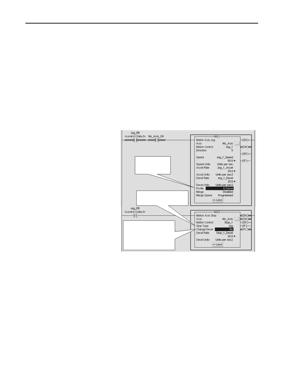
Explains why an axis might accelerate briefly before decelerating when a stop instruction is issued.
Provides corrective actions for issues like axis acceleration/deceleration and jog restart delays.
Explains potential causes for axis reversal when stopped and restarted, often related to S-curve profiles.
Details programming motion with the MDSC functionality, illustrating slave speed control from master.
Provides initial out-of-box settings for PowerFlex drives before application-specific configuration.
Lists recommended default settings for PowerFlex 527 and 755 drives for ramp velocity and current limits.
Explains how to set the ACO/AVO attribute for PowerFlex 527 drives to configure analog output for current or voltage.


