WebConsole - Switching Options
68
NX-Series Controllers - WebConsole & Programming Guide
Switching Page Components
The Switching page features the following components (labeled alphabetically to correspond to FIG. 57 on previous page):
Auto Take button (default is unselected) – when checked, this button persists the Auto Take function and remains illuminated until
unchecked. Once an input or output is selected, a click on an output for the input or on an input for an output will execute a switch.
This allows for quick cycling through several inputs for a selected output. Note that when a button is selected, it also appears in the
Configuration page with signal details (for button/signal details, click the Legend button).
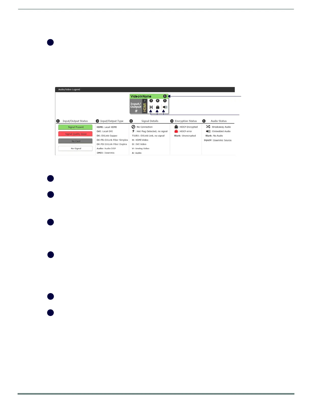
Legend button – click to open an additional browser tab (Audio/Video Legend) which displays the legend key with details regarding
the state of the input (source) and output (destination) connections. The browser tab opens in a tearaway tab/window that can be
dragged and dropped as a standalone desktop window for side-by-side reference with the Switcher/Configuration pages.
NOTE: The label on the title bar can be edited in the Input or Output Name field on the Configuration page.
NOTE: If the enclosure does not include a full set of input/output boards, input and output buttons for connectors that are not
available display with a gray Title bar (i.e., No Card).
Switch Mode buttons – click the A/V (default), Video, or Audio button to select the type of signal to be switched. These buttons
correspond to the available video and audio Virtual Matrices (VMs) in the system. For additional information on the Switch Mode,
see page 69.
Inputs section – this section contains buttons for each of the available input signals (per selected Switch Mode) in the system.
Click the input button that needs to be switched. Scroll bars on the right-hand side provide access to any inputs on large systems
which are not currently visible.
Downmix button – the Audio Switch Mode must be selected before the Downmix button displays. The input source used for the
downmix signal is selected on the Configuration page.
Outputs section – this section contains buttons for each of the available output signals in the system. Click the output button(s)
that needs to receive the signal from the currently selected input button. Note that when the currently selected button is an output,
it also appears in the Configuration page with signal details (for button/signal details, click the Legend button). Scroll bars on the
right-hand side provide access to any outputs on large systems which are not currently visible.
Select All and Deselect All buttons – these buttons appear only after an input is selected. Click as necessary to select or deselect all
output buttons.
Clear button – click to deselect all inputs and outputs (if selected, the Auto Take button state persists) and clear routing status in
the Configuration pane. Note that the Clear button does not disconnect switches. After the Clear button is selected and the input or
one of the outputs already routed is selected, the buttons turn blue to indicate current status. Selecting an output will show status
for the input routed to it, not the other outputs also routed from the same input.
Take button – click to execute the switch for the selected input and output(s). After the switch is made, the current content in the
Switching and Configuration pages persists until further action is taken. Note that the Take button is grayed out until one input and
one or more outputs have been selected for routing; once these conditions are met, the Take button becomes active. After the Take
button is clicked, all of the buttons clear their status.
Selected status bar (non-editable) – this status bar provides quick visual confirmation of input and output selections and their
status (blue = currently routed; yellow = ready to route, waiting further action; blue outline = currently routed, but deselected in
preparation to disconnect).
Switcher Setup button options are available on both the Switching page and the Configuration page.
Save and Load buttons – after a system has been set up per the installation’s requirements, the configuration values for the entire
switcher’s state (i.e., currently routed switches, video settings, and audio settings) can be saved and reloaded onto another
system(s) or backup system(s) for reuse. The file type is .xdg with XML content. When the Save button is clicked, the f ile is saved as
a managed content (non-editable text) file.
Title bar
Board state icons
 Loading...