Annunciators Power Connections for LCD and ACS Series Annunciators
146 IQ-301 PN 50036:F 10/29/2001
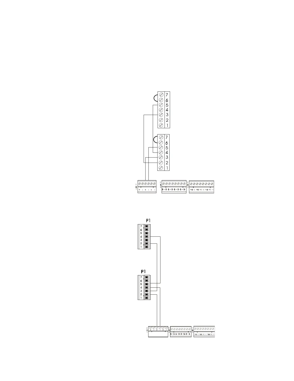
C.7 Power Connections for LCD and ACS Series Annunciators
This section shows how to wire power connections for ACS and LCD series
annunciators. Note the following when making power connections:
• All connections are power-limited.
• The power run to the LCD-80 or ACS annunciator does not require a Power
Supervision Relay because the loss of power is inherently supervised through
communication loss.
• The maximum LCD-80 current draw from power supply is 500 mA.
Figure 139 shows typical power wiring for ACS and LDM series annunciators:
Figure 138 Power Connections for LDM and ACS Series Annunciators
Figure 140 shows typical power wiring for LCD-80 series annunciators:
Figure 139 Power Connections for LCD-80 Series Annunciators
7) N.C. Trouble
6) Inputs
5) Common in (–)
4) Common out (–)
3) Power In (+24 VDC)
2) Power Out (+24 VDC)
1) Earth Ground
The ACM-8R does not
contain terminals 6 and 7.
TB1-3 (+)
TB1-4 (–)
Afp2annu
TB1-3 (+)
TB1-4 (–)
EIA-232 Transmit
EIA-232 Reference
- System Common OUT
- System Common IN
+24 VDC OUT
+24 VDC IN
EIA-232 Receive
EIA-232 Transmit
EIA-232 Reference
- System Common OUT
- System Common IN
+24 VDC OUT
+24 VDC IN
EIA-232 Receive
 Loading...