EasyManua.ls Logo

Ansul AUTOPULSE IQ-301 User Manual

Ansul AUTOPULSE IQ-301
196 pages
To Next Page IconTo Next Page
To Previous Page IconTo Previous Page
Page #190 background imageLoading...
Page #190 background image
CBE Programming How to Program CBE
190 IQ-301 PN 50036:F 10/29/2001
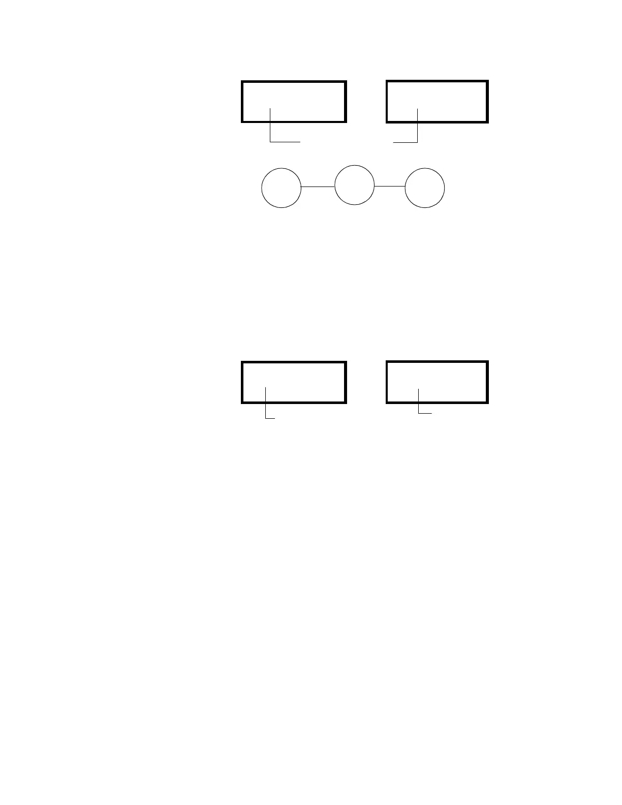
which puts Z05 into the CBE of D01 and M08. When detector D01 goes into alarm,
control module M08—and all devices and zones mapped to M08—also activate.
Figure 169 CBE Example 1
M.3.2 CBE Example 2
Program a Bell Circuit (B04) to activate a march time code.
1. Program Z98 (Code Type) to “March Time.” For instructions, refer to Section 3
“Programming”.
2. Program the Bell Circuit B04 to list Z98 in its CBE list.
3. When the Bell Circuit B04 activates, all devices connected to B04 will pulse with
the March Time code.
Figure 170 CBE Example 2
PROGRM@CONTROL
MODULE@ADDRESS@08
Z00@Z05@Z@@Z@@Z
@@@@@@@@@@@@@S*M08
PROGRM@SMOKE(PHOTO)
DETECTOR@ADDRESS@01
ZO3@Z05@Z@@@Z@@@Z@@
2.0%@@@@@@*P*@@@@D01
Both devices contain
zone Z05 in its CBE list
Software
Zone Z05
Detector
Zone Z05
Module
Zone Z05
PROGRM BELL CIRCUIT
PANEL CIRCUIT NO. 4
Z00@Z98@Z@@Z@@Z
SW B04
PRG@SOFTWARE@ZONE
CODE@TYPE:
MARCH@TIME
Z98
Z98 programmed for
March Time
B04 programmed with
Z98 in its CBE list

Table of Contents

Question and Answer IconNeed help?

Do you have a question about the Ansul AUTOPULSE IQ-301 and is the answer not in the manual?

Ansul AUTOPULSE IQ-301 Specifications

General IconGeneral
BrandAnsul
ModelAUTOPULSE IQ-301
CategoryFire Alarms
LanguageEnglish

Summary

Fire Alarm System Limitations

Smoke Detector Limitations

Explains how smoke detectors may fail to detect fires due to environmental factors or placement.

System Power and Compatibility Issues

Covers limitations related to electrical power supply and component compatibility.

Installation Precautions

Power and Wiring Safety

Warnings for electrical connections, power sources, and proper grounding.

Environmental and Component Handling

Guidance on operating environment, component care, and static discharge prevention.

Section 1 System Overview

1.1 General Description

Overview of the control panel and its capabilities.

1.3 Components

Details the physical parts of the system including panels, modules, and power.

1.4 Main Assemblies

Describes the core hardware units: CPU board, cabinet, LCD, and batteries.

Section 2 Installation

2.1 Preparing for Installation

Steps to take before installing the system, including unpacking and location selection.

2.2 Installation Checklist

A step-by-step checklist for installing, wiring, and testing system components.

2.4 AC and DC Power Connections

Instructions for connecting AC and DC power sources to the control panel.

2.9 Wiring a Signaling Line Circuit (SLC)

Core procedure for wiring the Signaling Line Circuit.

Section 3 Programming

3.1 Overview

Introduction to the control panel's programming capabilities.

3.3 Program Change Options

Overview of configurable program settings for system behavior.

3.4 How to Enter Program Change

Step-by-step guide to accessing and navigating program change mode.

Section 4 Operation

4.1 Overview

Introduction to operating the control panel and its functions.

4.3 How to Operate the Control Panel

Procedures for operating the panel in various conditions like normal, alarm, or trouble.

4.3.1 Normal Operation

Describes panel behavior and functions during normal operation.

4.3.4 Fire Alarm

How the panel indicates and operates during a fire alarm condition.

Appendix A Power Supply Calculations

A.2 Calculating the AC Branch Circuit

Procedure for calculating AC branch circuit requirements.

A.4 Calculating the System Current Draw

Method for calculating the total system current draw under various conditions.

A.5 Calculating the Battery Size

How to calculate the required battery size for system backup.

Appendix D Releasing Applications

D.2 Programming Releasing Zones

Instructions for programming the four software releasing zones.

D.2.1 Releasing Zone Functions

Details on functions available within releasing zones.

Appendix E Combination Fire/Burglary Applications

E.2 Installation

Steps for installing a combination fire/burglary system.

E.3 Programming

Programming the control panel for security functions.

Appendix F Wire Requirements

SLC Loop (power-limited)

Critical wiring requirements for the Signaling Line Circuit.

Appendix K UL Power-limited Wiring Requirements

K.1 Overview

Guidelines for UL power-limited and nonpower-limited wiring.

K.2 Typical Circuit with Nonpower-limited and Power-limited Wiring

Illustrates typical wiring separation for power-limited circuits.

Appendix M CBE Programming

M.3 How to Program CBE

Instructions on how to program Control-By-Event functions.

Appendix N External Battery Charger

N.3 Mounting the CHG-120

Instructions for mounting the CHG-120 charger in various cabinets.

N.4 Connecting the CHG-120

Instructions for connecting the CHG-120 charger to the IQ-301 panel.

Related product manuals