Installation Wiring a Signaling Line Circuit (SLC)
46 IQ-301 PN 50036:F 10/29/2001
2.9.8 Wire Requirements for a Four-wire SLC
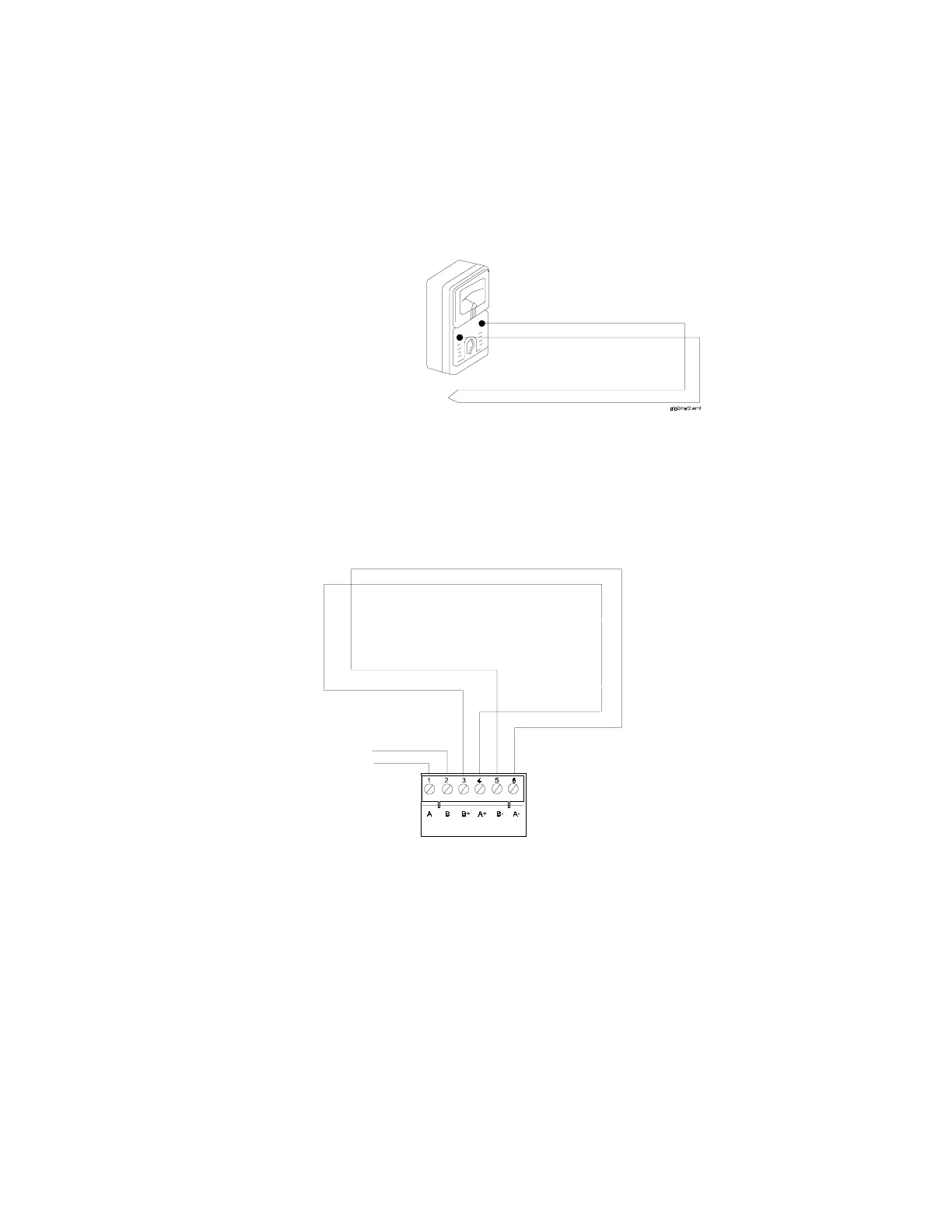
Measuring Loop Resistance for a Four-wire SLC
The total DC resistance of the SLC pair cannot exceed 40 ohms. Measure DC resistance
as shown in Figure 25. For detailed UL wiring requirements, refer to Appendix F.
1. Disconnect the SLC Out and SLC Return at the control panel.
2. Short the two leads of SLC Return.
3. Measure the resistance across the SLC Out leads (Figure 25).
Figure 25 Meter Leads for Measuring a Four-wire SLC
Measuring Total Wire Length for a Four-wire SLC
The total length of wire (12 AWG) in a four-wire SLC cannot exceed 10,000 feet (3048
m). Figure 26 identifies the output and return loops from SLC terminal TB5 on the
CPU:
Figure 26 Measuring the Wire Length – Four-wire SLC
SLC Out
SLC Return
T-Tapping is not allowed
on a four-wire SLC.
CPU
SLC A (loop return)
SLC B (output loop)
no connection
TB5
 Loading...