Installation Wiring a Signaling Line Circuit (SLC)
60 IQ-301 PN 50036:F 10/29/2001
address on the base and on the head.
4. Install the intelligent detector head.
Wiring an Intelligent Detector to an SLC
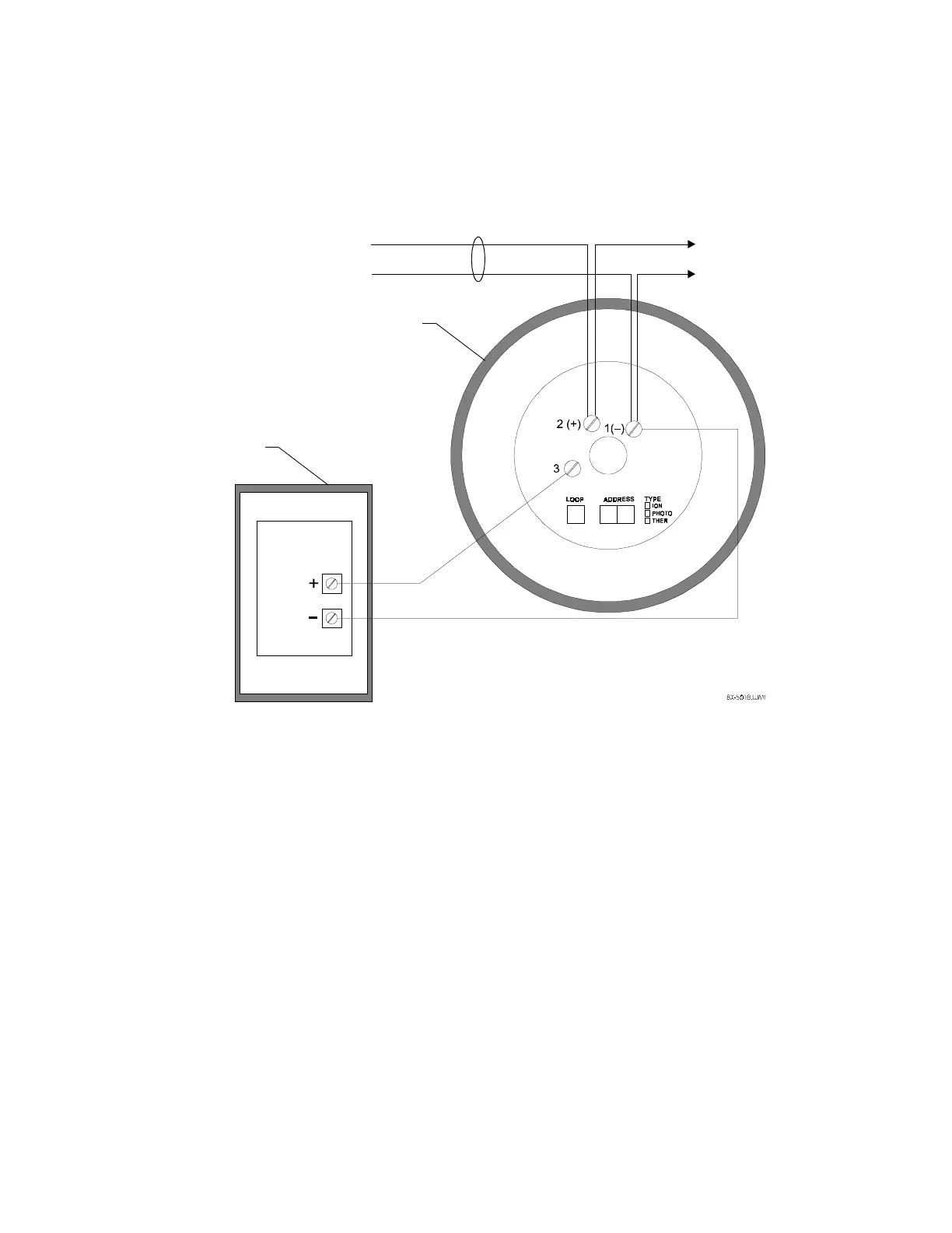
Figure 42 shows typical wiring of a detector (wired to a RA400Z remote annunciator)
connected to an SLC:
Figure 42 Typical Wiring of a Detector Base to an SLC
2.9.14 SLC Wiring with an NBG-12LX Addressable Manual
Pull Station
The NBG-12LX is an addressable manual pull station with a key-lock reset feature.
Figure 43 shows typical wiring and provides instructions for setting the SLC address.
1. Connect the SLC to terminal screws (+) and (–).
2. Connect the NBG-12LX to the CPU as shown in Figure 43.
3. Set the SLC address of the pull station. Rotary switches are located on the interior
of the pull station, as shown in Figure 43. The address is set the same way as for
control, monitor & relay modules (refer to “Setting an SLC Address for a Module”
on page 44). Factory preset is address 00. Record the device address and SLC
number on the label inside the pull station.
Note: In the sample shown below, the switches are set to address 12.
Detector Base
Channel (+)
Channel (–)
to next device
on SLC
Channel (+)
Channel (–)
RA400Z Remote
LED Annunciator
SLC
 Loading...