Installation Standard Relays (TB3)
36 IQ-301 PN 50036:F 10/29/2001
2.6.2 Releasing Circuits
Any or all of these circuits may be used as a releasing circuit by programming it for
RELEASE CKT. For information on programming releasing circuits, refer to “How to
Program a Panel Circuit” on page 84 and Appendix D “Releasing Applications”.
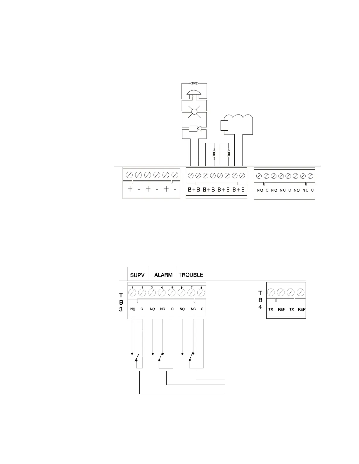
Figure 12 Output Circuit Connections (TB2)
2.7 Standard Relays (TB3)
The control panel provides a set of Form-C alarm and a set of Form-C trouble contacts
rated for 2.0 A @ 30 VDC (resistive). The control panel also provides a Form-A
supervisory contact rated for 2.0 A @ 30 VDC (resistive).
Figure 13 Relay Connections (TB3)
T
B
3
T
B
2
T
B
1
1
1
2
2
3
3
4
4
5
5
6
6
7
7
8
8
+ -
+ -
Polarized Horn
Polarized Strobe
Style Y Notification
Appliance Circuit
(supervised and
power-limited)
Releasing Circuit
(supervised and
power-limited)
Dummy Load all
unused Circuits 4.7K,
1/2-Watt
REL-4.7K
4.7K, 1/2-Watt (PN 71252 UL-listed)
+ –
Note: Notification circuit polarity
shown in alarm state.
Polarized Bell
afpoc.wmf
Form-C contacts
Form-A contact
 Loading...