UL Power-limited Wiring Requirements Overview
186 IQ-301 PN 50036:F 10/29/2001
Appendix K UL Power-limited Wiring Requirements
K.1 Overview
This appendix provides guidelines for power-limited and nonpower-limited UL wiring
requirements. Figure 167 shows typical wiring for a circuit with power-limited and
nonpower-limited wiring that meets UL requirements, which are as follows:
• Power-limited and nonpower-limited circuit wiring must remain separated in the
cabinet
• All power-limited circuit wiring must remain at least 0.25 inch (6.35 mm) away
from any nonpower-limited circuit wiring.
• Power-limited and nonpower-limited circuit wiring cannot enter and exit the
cabinet through the same knockout or conduits. Separate power-limited and
nonpower-limited wiring as shown in Figure 167.
K.2 Typical Circuit with Nonpower-limited and Power-limited Wiring
Note: For complete information on wiring an RTM-8 module, refer to “Installing an
RTM-8 Module” on page 63.
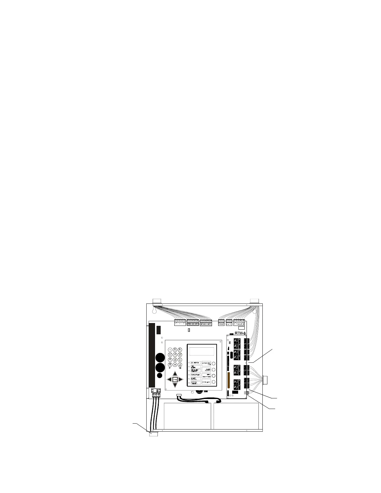
Figure 167 shows the RTM-8 module installed in the AUTOPULSE IQ-301 cabinet.
Observe the following:
• Power-limited and nonpower-limited wiring maintain a minimum distance of
0.25 inch (6.35 mm) wire-to-wire.
• A 0.75 inch (19.05 mm) gap exists between relay 4 and relay 5. If using this
module to drive both power-limited and nonpower-limited circuits, use relays 1-4
to drive power-limited circuits and relays 5-8 to drive nonpower-limited circuits.
Using relays 5-8 for nonpower-limited circuits allows grouping them with the
transmitter output nonpower-limited wiring.
• If using all relays as power-limited circuits, the 0.25 inch (6.35 mm) gap between
relay 8 and the nonpower-limited transmitter output terminal meets UL
power-limited wiring requirements.
Figure 167 Typical Wiring Diagram for UL Power-limited Requirements
Power-limited circuits
Nonpower-limited
circuits
0.75-inch gap (19.05 mm)
between power-limited
and nonpower-limited
circuits
Power-limited circuits
Nonpower-limited
transmitter output
terminal
AC Power
0.25-inch (6.35 mm)
gap
 Loading...