Installation EIA-232 Devices – Remote Printers and CRTs (TB4)
38 IQ-301 PN 50036:F 10/29/2001
Connection between the control panel and the PRN is via an EIA-232 interface. A
custom cable must be assembled for connection to the printer's EIA-232 port.
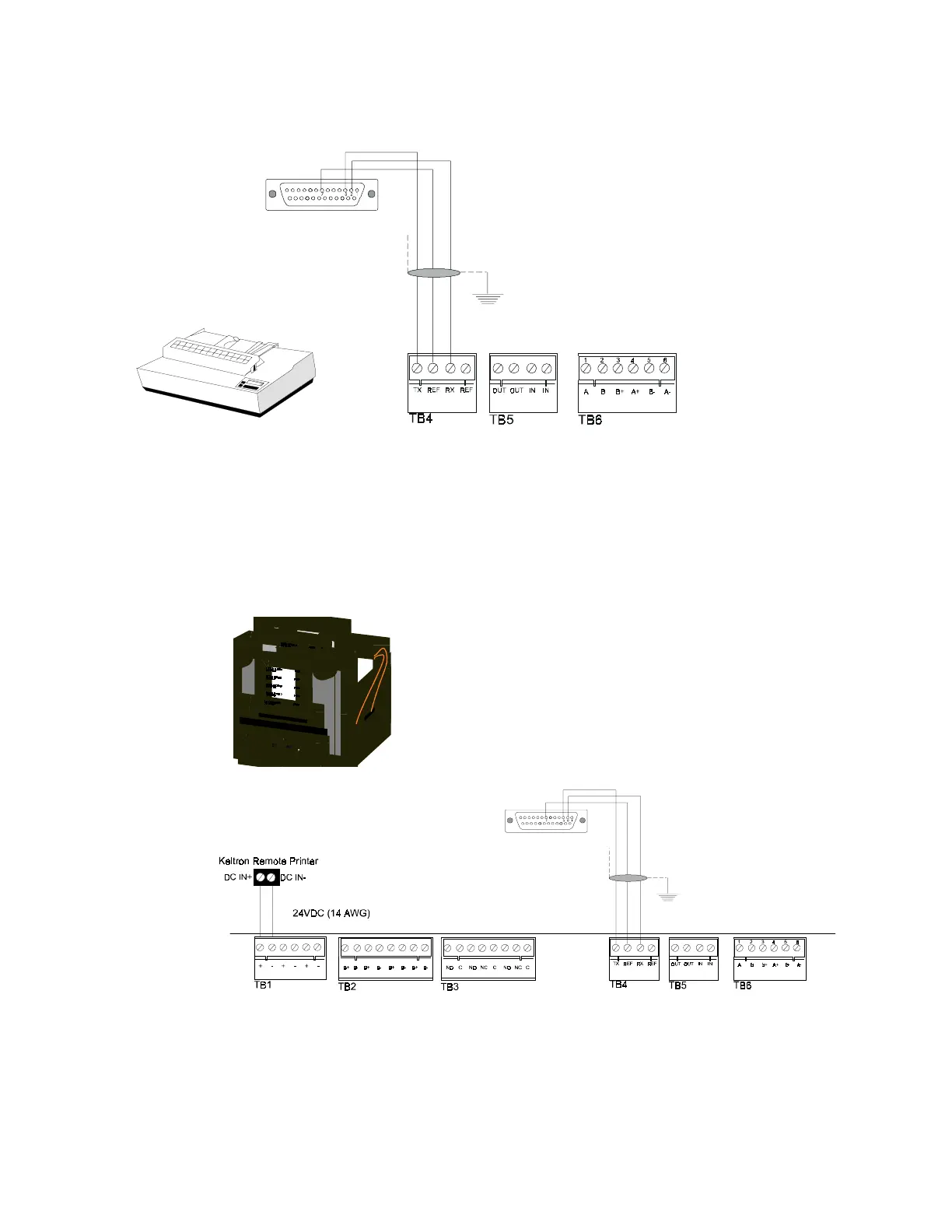
Figure 14 Remote Printer Connections
2.8.4 Keltron Printer
Figure 15 shows typical connections between the control panel and a Keltron printer.
Figure 15 Keltron Printer Connections
Notes on Figure 15:
1. Outputs are power-limited, but are not supervised.
2. Connections must be made with overall foil/braided-shield twisted paired cable
DB-25 Connections:
Connect TX (Pin 3) to TB4 terminal 1
Connect REF (Pin 7) to TB4 terminal 2
Connect RX (Pin 2) to TB4 terminal 3
Note: When using a DB-25 for Upload/Download connect a
jumper between pin 6 and pin 20.
DB-9 Connections:
Connect TX (Pin 2) to TB4 terminal 1
Connect REF (Pin 5) to TB4 terminal 2
Connect RX (Pin 3) to TB4 terminal 3
Note: If also using a DB-9 connector for upload/download
connect a jumper between pin 4 and pin 6.
Plug the DB-9 or DB-25
connector into the EIA-232
port of the printer.
The EIA-232 printer interface may also be used
with EDP UL-listed equipment, such as personal
computers, to monitor the control panel for
supplementary purposes.
Keltron Printer
Model number VS4095/5
(see note 3)
Plug this DB-25 connector into the
EIA-232 port of the printer
 Loading...