ACS and LDM Series EIA-485 Connections Annunciators
IQ-301 PN 50036:F 10/29/2001 147
C.8 ACS and LDM Series EIA-485 Connections
Refer to the LDM and ACS
manuals for additional
information.
This section shows how to connect ACS and LDM series annunciators to the control
panel, subject to the following:
• Maximum number allowed – A maximum of 10 point annunciators (such as
ACM, LDM, AFM) can be connected to this circuit when powered by the control
panel.
• Maximum distance – There is a 6,000 foot (1828.8 m) maximum distance (16
AWG) between the control panel and the furthest annunciator.
• Cable – Use twisted pair cable with a characteristic impedance of approximately
120 ohms.
• Circuit rating – The EIA-485 circuit is rated 5.5 VDC max., 60 mA max.
• Connections – All connections are power-limited and supervised.
Connect the EIA-485 circuit as follows:
1. Connect each annunciator to 24 VDC operating power (power-limited and
supervised) to the AUTOPULSE IQ-301 as shown in Figure 139 on page 146.
2. Set SW2 on the control panel to the “ACS” position (right position).
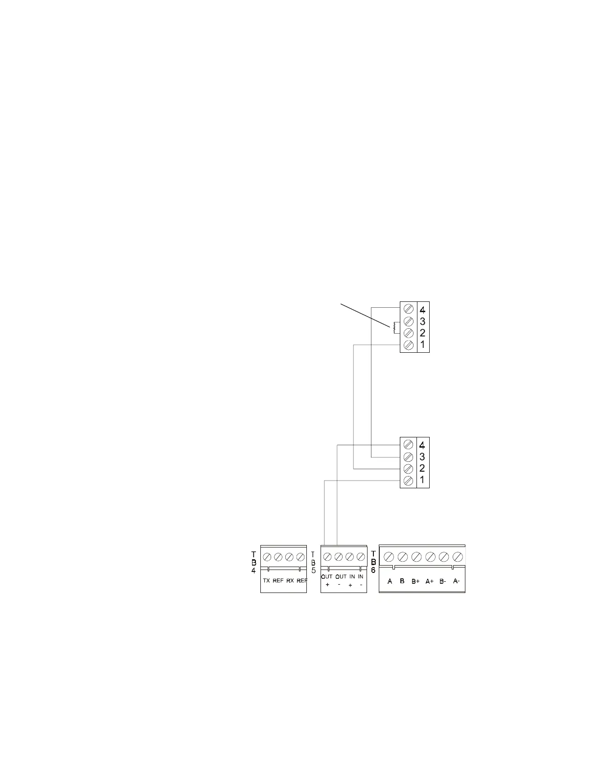
Figure 140 ACS and LDM Series EIA-485 Connection
Install 120 ohm terminating
resistor on last annunciator.
TB5-1 (+)
TB5-2 (–)
TB2
TB2
EIA-485 In (–)
EIA-485 Out (–)
EIA-485 Out (+)
EIA-485 In (+)
 Loading...