R5906113 /08 UDX 83
7.4 Installation of the GSM module
WARNING: The procedures below may only be performed by Barco trained and qualified
technicians.
CAUTION: Always wear a wrist band which is connected to the ground while handling the
electrostatic discharge (ESD) sensitive parts.
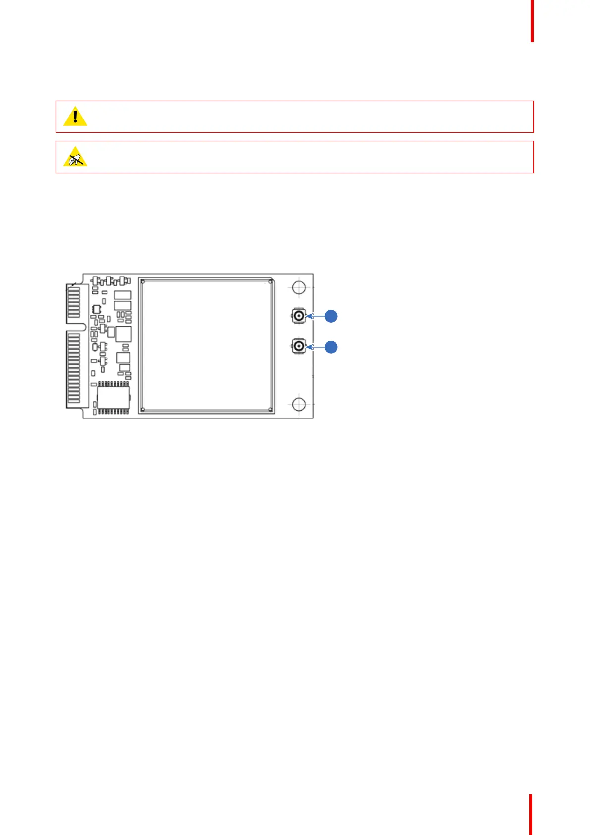
About the two antenna connectors
While the GSM module has two antenna connectors, only one of them can be used: the main RF antenna
(reference 2, Image 7-9).
The secondary antenna (reference 1) is an RX diversity antenna, but is not enabled when the GSM module is
plugged into the communication module.
Image 7-9: Overview GSM module
1 RX Diversity antenna (DIV)
2 Main RF antenna (ANT)
Required tools
Phillips screwdriver PH1
Required parts
SIM card (not delivered)
How to install
1. Remove the Communication board.
2. Remove the drive fastener (1) from the front side of the Communication module.
WiFi & GSM Module
 Loading...