56
7113868.01 - en
INSTRUCTIONS FOR FITTERS
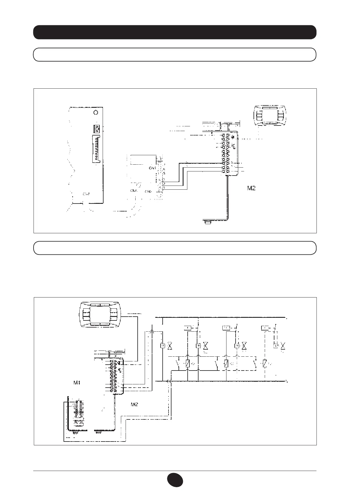
A relay is available for the external auxiliary controls. Connect terminals 1-2-3 of connector CN1 on the relay board to the
respective terminals 10-9-8 of terminal board M2.
29. ELECTRICAL CONNECTION TO A ZONE SYSTEM
29.1 CONNECTION OF THE RELAY BOARD
Figure 18
Connect the contact relative to heating requests in zones that are not controlled by the remote control device in parallel
to terminals 1-2 “TA” on terminal board M1.
Remove the jumper.
The zone controlled by the remote control device is managed by the zone 1 solenoid, as illustrated in gure 19.
29.2 CONNECTING THE ZONES
IMPORTANT: make sure parameter F04 = 2 (as per factory setting – section 20).
Figure 19
CG_1840 7 1102_1704
BOILER BOARD
RELAY BOARD
RELAY 2
RELAY 1
CG_1825 / 1102_1705
ZONE 1
ZONE 1
(REMOTE CONTROL UNIT
ZONE 2
(AMBIENT THERMOSTAT)
ZONE 3
(AMBIENT THERMOSTAT)
ZONE N
(AMBIENT THERMOSTAT)
Electrovalve
ZONE 1
 Loading...