59
7113868.01 - en
INSTRUCTIONS FOR FITTERS
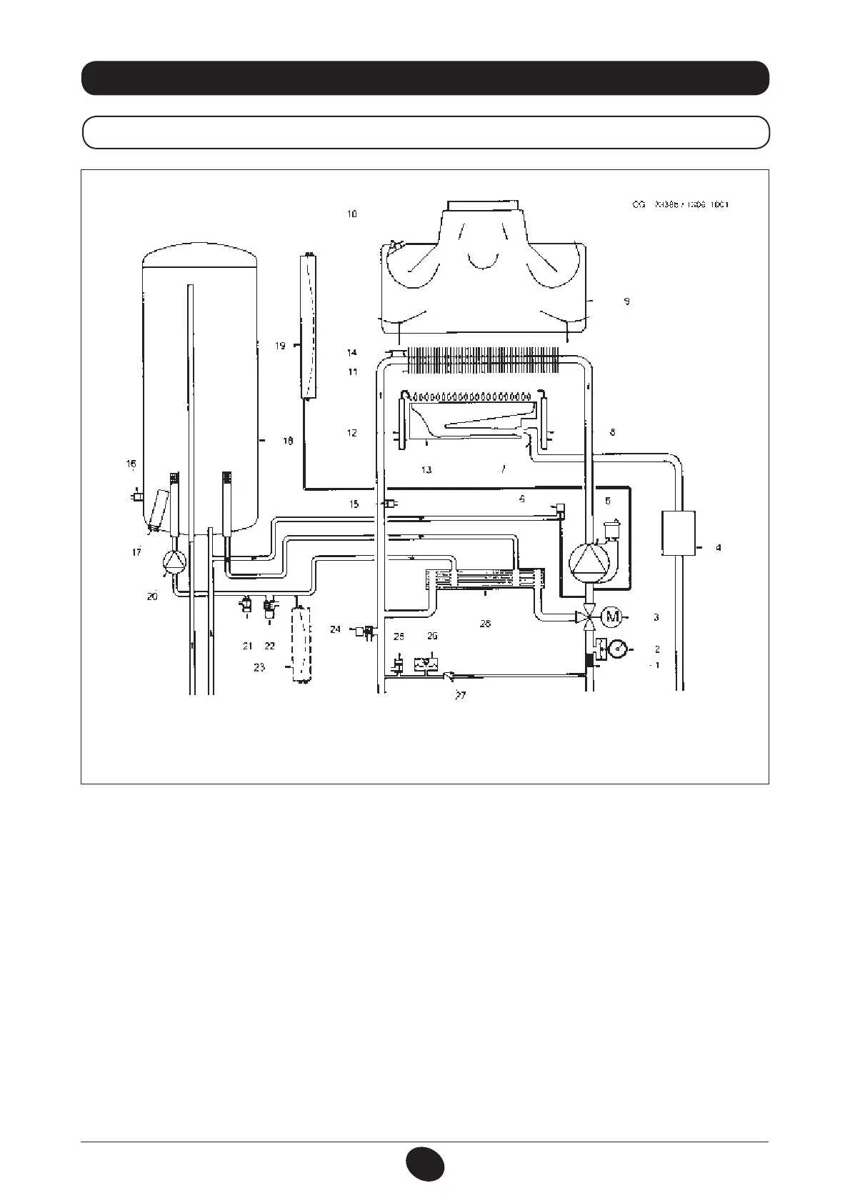
35. FUNCTIONAL CIRCUIT DIAGRAM
240 i - 280 i
1 heating lter
2 pressure gauge
3 powered 3-way valve
4 gas valve
5 heating circuit pump with deaerator
6 boiler lling tap
7 gas train with injectors
8 ame detection electrode
9 fumes conveyor
10 fumes thermostat
11 water-fumes exchanger
12 ame ignition electrode
13 burner
14 safety thermostat
15 NTC heating probe
16 NTC domestic hot water sensor
17 sacricial anode
18 storage boiler
19 heating circuit expansion vessel
20 DHW circuit pump
21 storage boiler drain tap
22 DHW circuit safety valve
23 DHW circuit expansion vessel (accessory)
24 boiler safety valve
25 boiler drain tap
26 hydraulic pressure switch
27 check valve on automatic by-pass
28 plate exchanger
Key:
Figure 21
DHW
outlet
DHW
inlet
heating delivery heating return gas inlet
 Loading...