9-198
Cisco IOS XR Troubleshooting Guide for the Cisco CRS-1 Router
OL-21483-02
Chapter 9 Troubleshooting Memory
Watchdog System Monitor
The definition of the node state thresholds depends on the size of the physical memory. For instance, on
a node with 2 GB of physical memory, the memory state is considered NORMAL as long the free
memory is greater than 48 MB.
If a memory threshold is crossed, wdsysmon immediately checks if a process has exceeded its memory
limit. All such processes are stopped after a debug script runs on the process identifier (PID) to collect
detailed information on the memory hog. If memory usage is still high after this step, wdsysmon sends
notifications to registered clients. Clients can then take preventive and recovery actions.
The memory state can be verified using the show watchdog memory-state location node-id command.
The following example shows node 0/RP0/CPU0 as in the normal memory state.
RP/0/RP0/CPU0:router# show watchdog memory-state location 0/rp0/cpu0
Memory information:
Physical Memory: 4096 MB
Free Memory: 3485.671 MB
Memory State: Normal
If the memory state is changing from normal to minor use the show processes memory [job-id] location
node-id command to list top memory users and identify possible memory leaks. After top memory users
have been identified, use the memory usage analyzer to discover the processes causing a memory leak.
See the “Memory Usage Analyzer” section on page 9-202. Your technical representative should now be
involved to collect the appropriate data and take the corresponding actions such as process restart.
Wdsysmon has a procedure to recover from memory-depletion conditions. When wdsysmon determines
that the state of a node is severe, it attempts to find a process, or set of processes, that have likely leaked
memory leading to the depletion condition. The process or set of processes are stopped to recover the
memory. This situation should be avoided by regularly checking the watchdog memory state.
Configuring and Displaying Memory Thresholds
Memory thresholds can be configured. Threshold values can be applied to all cards, or unique threshold
settings can be applied to specific cards. If the local threshold settings are removed, the local settings
return to those set globally. In addition, you can view default and configured thresholds.
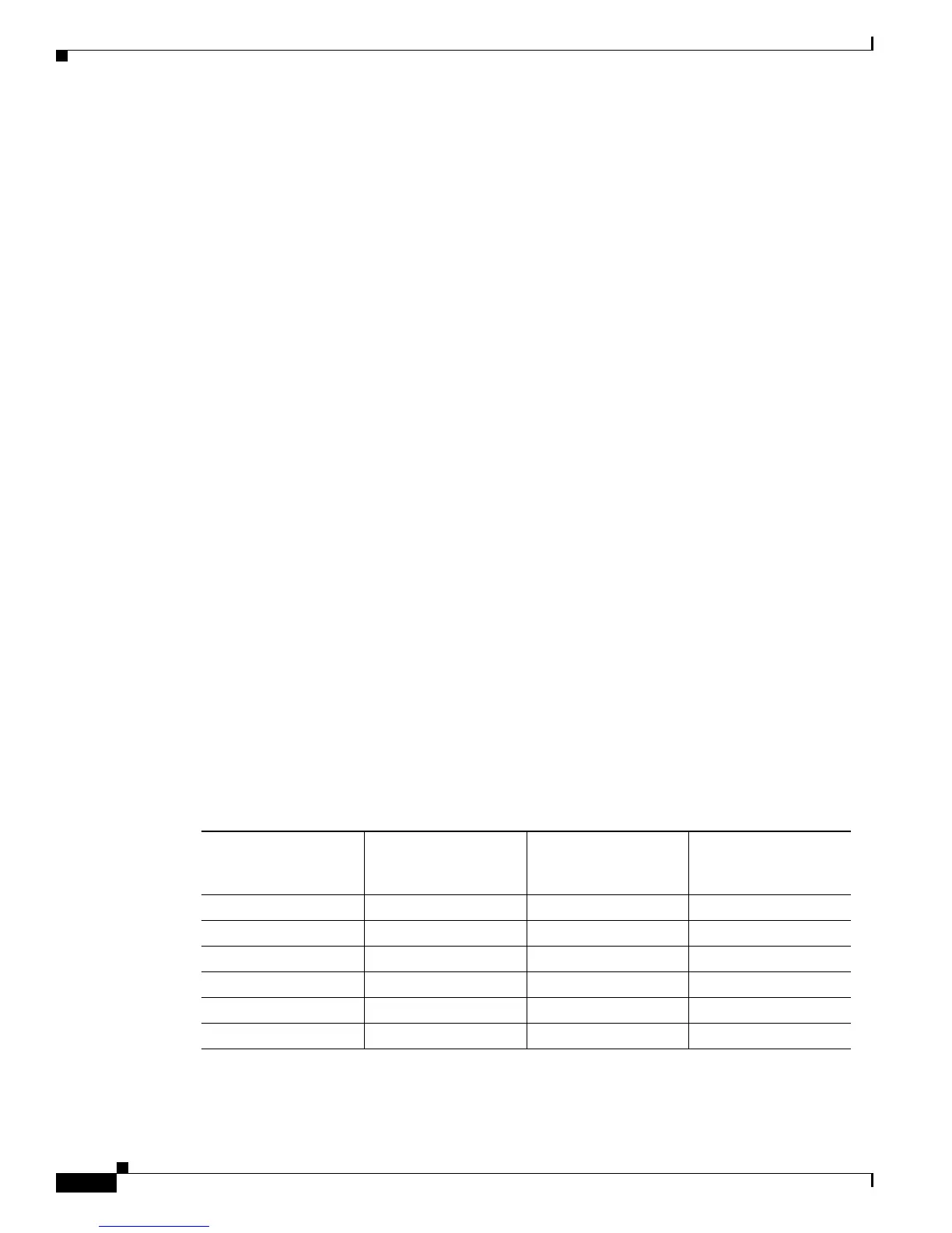
Table 9-1 provides the recommended memory threshold value calculations if the minor threshold is set
to 20 percent, the severe threshold is set to 10 percent, and the critical threshold is set to 5 percent.
To identify, configure, and display memory thresholds, perform the following procedure.
Table 9-1 Recommended Memory Threshold Values
Total Available
Memory (MB)
Minor Threshold (20
percent of available
memory)
Severe Threshold (10
percent of available
memory)
Critical Threshold (5
percent of available
memory)
128 25.6 12.8 6.4
256 51.2 25.6 12.8
512 102.4 51.2 25.6
1024 204.8 102.4 51.2
2048 409.6 204.8 102.4
4096 819.2 409.6 204.8
 Loading...


