User's Manual
14
2.3 Alarm Connection
2.3.1 Alarm Port
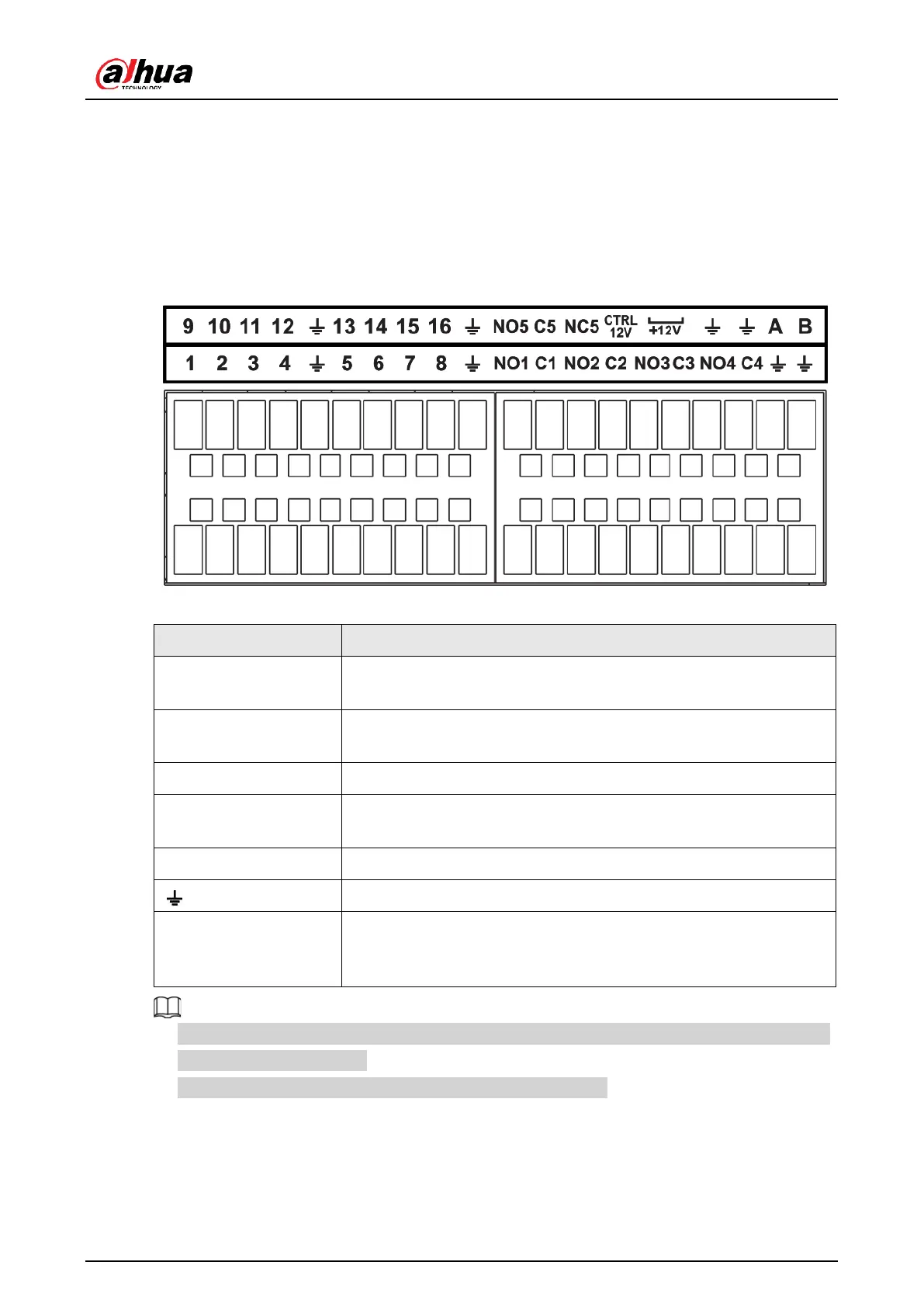
The alarm port is shown as below. The following figure is for reference only.
Figure 2-97 Alarm port
Table 2-45 Alarm port description
ALARM1–ALARM16. The alarm becomes activated in the low
level.
NO1 C1, NO2 C2, NO3
C3, NO4 C4
Four NO activation output groups. (On-off button).
One NO/NC activation output group. (On-off button).
Control power output. Disable power output when alarm is
canceled. Current is 500 mA.
Rated current output. Current is 500 mA.
485 communication port. They are used to control devices such
as PTZ. Please parallel connect 120 TΩ between A/B cables if
there are too many PTZ decoders.
●
Different models support different alarm input ports. Please see the specifications sheet
for detailed information.
●
Slight difference might be found on the alarm port layout.
2.3.2 Alarm Input Port
Connect the positive end (+) of the alarm input device to the alarm input port (ALARM IN 1–
 Loading...