Parameter 7-10 Torque PI Feedback Source
Parameter 7-12 Torque PI Proportional Gain
Parameter 7-13 Torque PI Integration Time
Parameter 7-16 Torque PI Lowpass Filter Time
Table 457: Parameter 7-16 Torque PI Lowpass Filter Time
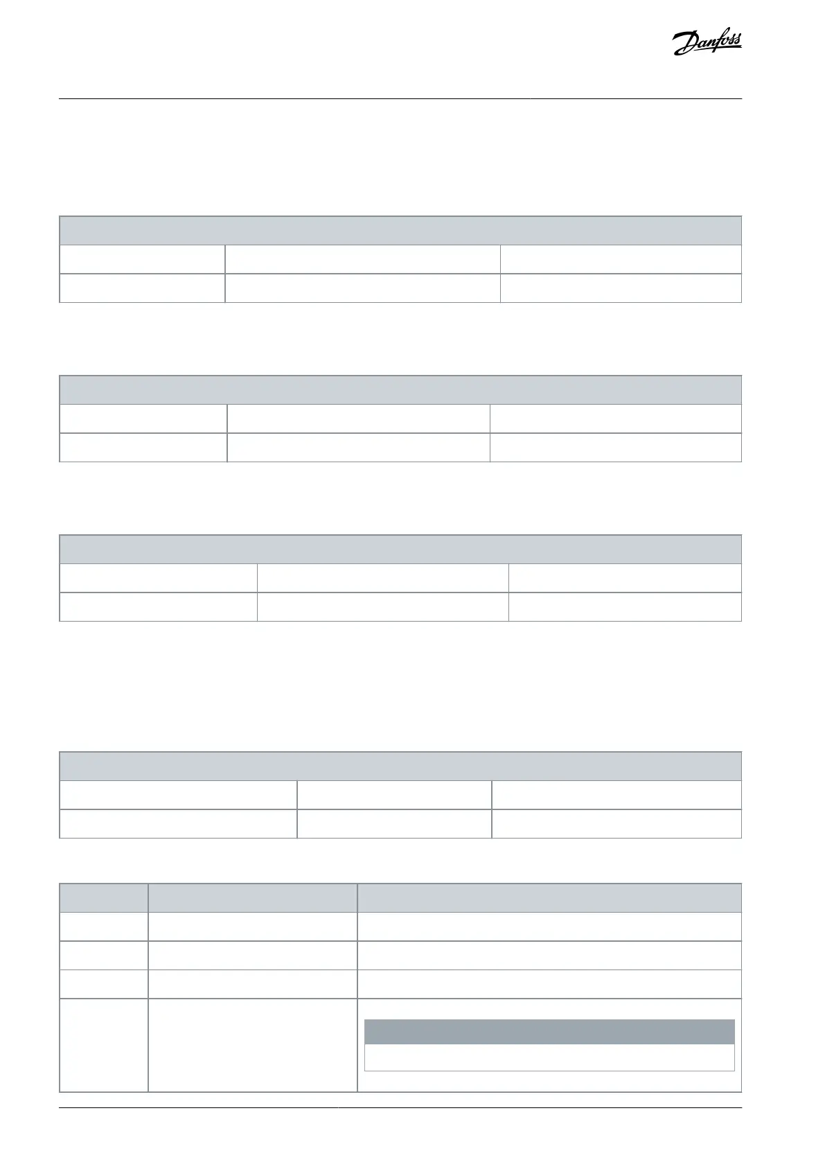
7-16 Torque PI Lowpass Filter Time
Parameter type: Range, 0.1 - 100 ms
Change during operation: True
Enter the time constant for the torque control low-pass filter.
Parameter 7-18 Torque PI Feed Forward Factor
Table 458: Parameter 7-18 Torque PI Feed Forward Factor
7-18 Torque PI Feed Forward Factor
Parameter type: Range, 0 - 100%
Change during operation: True
Enter the torque feed-forward factor value. The reference signal bypasses the torque controller by this value.
Parameter 7-19 Current Controller Rise Time
Table 459: Parameter 7-19 Current Controller Rise Time
7-19 Current Controller Rise Time
Default value: Size related
Parameter type: Range, 15 - 100%
Change during operation: True
Enter the value for the rise time of the current controller as a percentage of the control period.
5.8.5 7-2* Process Ctrl. Feedb.
Select the feedback sources for the process PID control,and how this feedback should be handled.
Parameter 7-20 Process CL Feedback 1 Resource
Table 460: Parameter 7-20 Process CL Feedback 1 Resource
7-20 Process CL Feedback 1 Resource
Default value: [0] No function
Change during operation: True
The effective feedback signal is made up of the sum of up to 2 different input signals. Select which drive input should be treated as
the source of the 1
st
of these signals. The 2
nd
input signal is defined in parameter 7-22 Process CL Feedback 2 Resource.
N O T I C E
This option is only available in FC 302.
AU275636650261en-000101 / 130R0334260 | Danfoss A/S © 2022.12
Parameter Descriptions
VLT AutomationDrive FC 301/302
Programming Guide
 Loading...


