Parameter 12-99 Media Counters
Table 669: Parameter 12-99 Media Counters
Parameter type: Range, 0 - 4294967295
Change during operation: True
This parameter is read-only. Advanced interface counters from a built-in switch can be used for low-level troubleshooting. The pa-
rameter shows a sum of port 1 + port 2.
5.13 Parameter Group 13-** Smart Logic Control
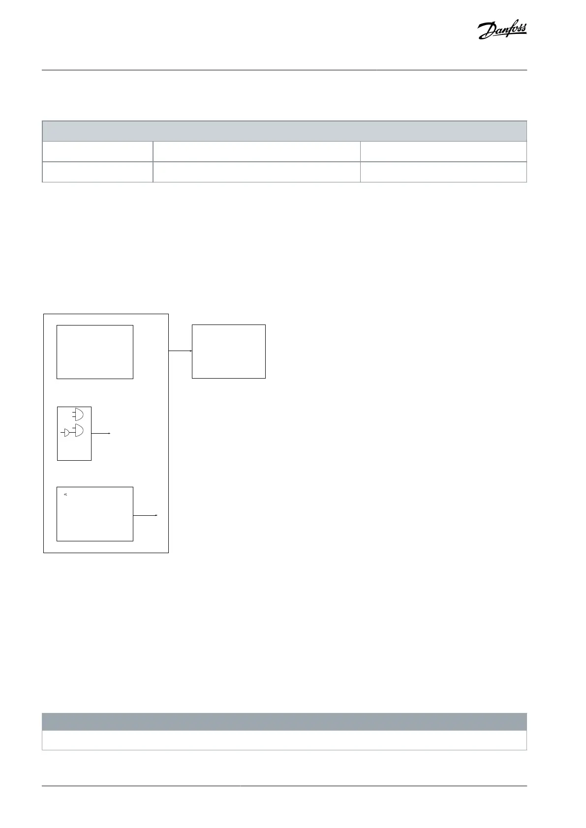
Smart logic control (SLC) is a sequence of user-defined actions (see parameter 13-52 SL Controller 1 Action) executed by the SLC when
the associated user-defined event (see parameter 13-51 SL Controller 1 Event) is evaluated as true by the SLC. The condition for an
event can be a particular status, or that the output from a logic rule or a comparator operand becomes true. That leads to an associ-
ated action as illustrated:
Par. 13-11
Comparator Operator
Par. 13-43
Logic Rule Operator 2
Par. 13-51
SL Controller Event
Par. 13-52
SL Controller Action
e30bb671.14
Coast
Start timer
Set Do X low
Select setup 2
. . .
Running
Warning
Torque limit
Digital input X 30/2
. . .
=
TRUE longer than..
. . .
. . .
Illustration 77: Smart Logic Control (SLC)
Events and actions are each numbered and linked in pairs (states). This means that when the 1
st
event is fulfilled (becomes true), the
1
st
action is executed. After this, the conditions of the 2
nd
event are evaluated and if evaluated true, the 2
nd
action is executed, and
so on. Only 1 event is evaluated at any time. If an event is evaluated as false, nothing happens (in the SLC) during the current scan
interval and no other events are evaluated. This means that when the SLC starts, it evaluates the 1
st
event (and only the 1
st
event) in
each scan interval. Only when the 1
st
event is evaluated as true, the SLC executes the 1
st
action and starts evaluating the 2
nd
event.
It is possible to program 1–20 events and actions. When the last event/action has been executed, the sequence starts over again
from the 1
st
event/action.
Four concurring sequences can be defined with each up to 20 event and action pairs. The sequences are executed at the same time
but operate separately. For example, sequence 1 may have executed 3 actions, while sequence 2 still waits for its 1
st
event to occur.
In this example, parameter 13-00 SL Controller Mode [0], parameter 13-01 Start Event [1], and parameter 13-02 Stop Event [2] corre-
spond to sequence 1, sequence 2, sequence 3, and the like.
N O T I C E
Comparators Flip-Flops, timers, and logic rules are shared between sequences.
AU275636650261en-000101 / 130R0334372 | Danfoss A/S © 2022.12
Parameter Descriptions
VLT AutomationDrive FC 301/302
Programming Guide
 Loading...


