6. Remove the fan.
7. Remove the system board.
About this task
NOTE: The system board can be removed with the heat sink attached in order to simplify the procedure and preserve the
thermal bond between the system board and heat sink.
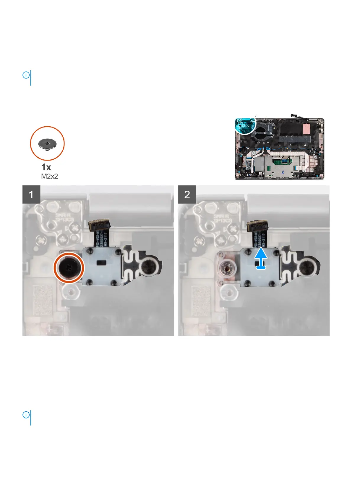
The following images indicate the location of the power-button with optional fingerprint reader and provide a visual
representation of the removal procedure.
Steps
1. Remove the (M2x2) screw that secures the power button with optional fingerprint reader to the palm-rest assembly.
2. Lift the power button with optional fingerprint reader and cable out of the system.
Installing the power button with optional fingerprint reader
About this task
NOTE:
The system board can be installed with the heat sink attached in order to simplify the procedure and preserve the
thermal bond between the system board and heat sink.
The following images indicate the location of the power button with optional fingerprint reader and provide a visual
representation of the removal procedure.
Removing and installing components
59
 Loading...