VFD-V Series
DELTA ELECTRONICS, INC. ALL RIGHTS RESERVED
5-72
Definition Parameter Address Function
2104H output current (XX.XX)
2105H DC-BUS voltage (XXX.X)
2106H output voltage (XXX.XX)
2107H presently-executed step speed
2109H residual time after procedural operating the
step speed
2116H multi-function display (Pr. 00-04)
2120H
2122H
217EH
(00-04=0)
(00-04=1)
(00-04=47)
5. Additional Response during Erroneous Communication:
If errors occurred when the drive is conducting the communication connection, the drive
will respond to this error and then respond (send) the Function code AND 80H to the
master control system so that the system will be informed of the error. And at the same
time, the keypad display panel of the drive will show “CE-XX” as a warning message, and
“XX” is then the error code. Please refer to “Meaning of the Error Codes” during the
communication.
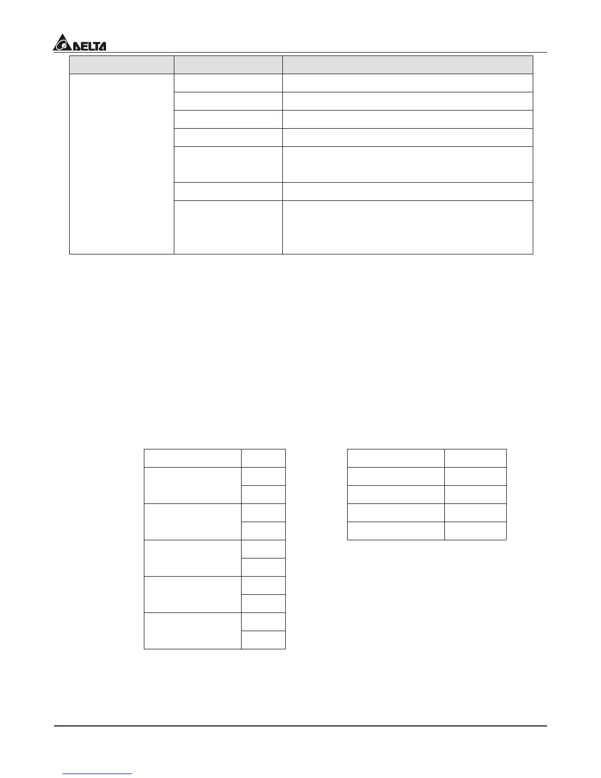
For example:
The ASCII Mode: The RTU Mode:
STX ‘:’ Address 01H
‘0’ Function 86H Address
‘1’ Exception code 02H
‘8’ CRC CHK Low C3H Function
‘6’ CRC CHK High A1H
‘0’ Exception code
‘2’
‘7’ LRC CHK
‘7’
CR END
LF

 Loading...