VFD-V Series
DELTA ELECTRONICS, INC. ALL RIGHTS RESERVED
3-14
3.6 Wiring Notice
1. There are corresponding ring terminals which will be included with each unit (15-30HP),
and please use the proper crimping tool by KST INC. P/N: KST-HDC38A for securing
the conductor.
2. When wiring up, and that the wiring route specifications are settled, please conduct the
wiring following the electrician regulations.
3. The connection between the three-phase AC input power and the main circuit terminal
R/L1, S/L2, T/L3 has to set up a none-fusing switch in between. The best is to series
connect with an electro-magnetic contactor (MC) so as to cut off the power supply at the
same time when the inverter protection function acts. (The two ends of the
electro-magnetic contactor should have the R-C Varistor).
4. There is no phase-order differentiation in the input power R/L1, S/L2, T/L3 and users
could connect with either one of use.
5. The ground terminal E is grounded with the third-type grounding method (with the
grounding impedance under 100
Ω
).
6. The grounding wire of the inverter could not be grounded at the same time with
machinery with grand current loading, like that of the electric soldering machine and of
the motor with grand horsepower; they have to be grounded individually.
7. The shorter the ground wire, the better it is.
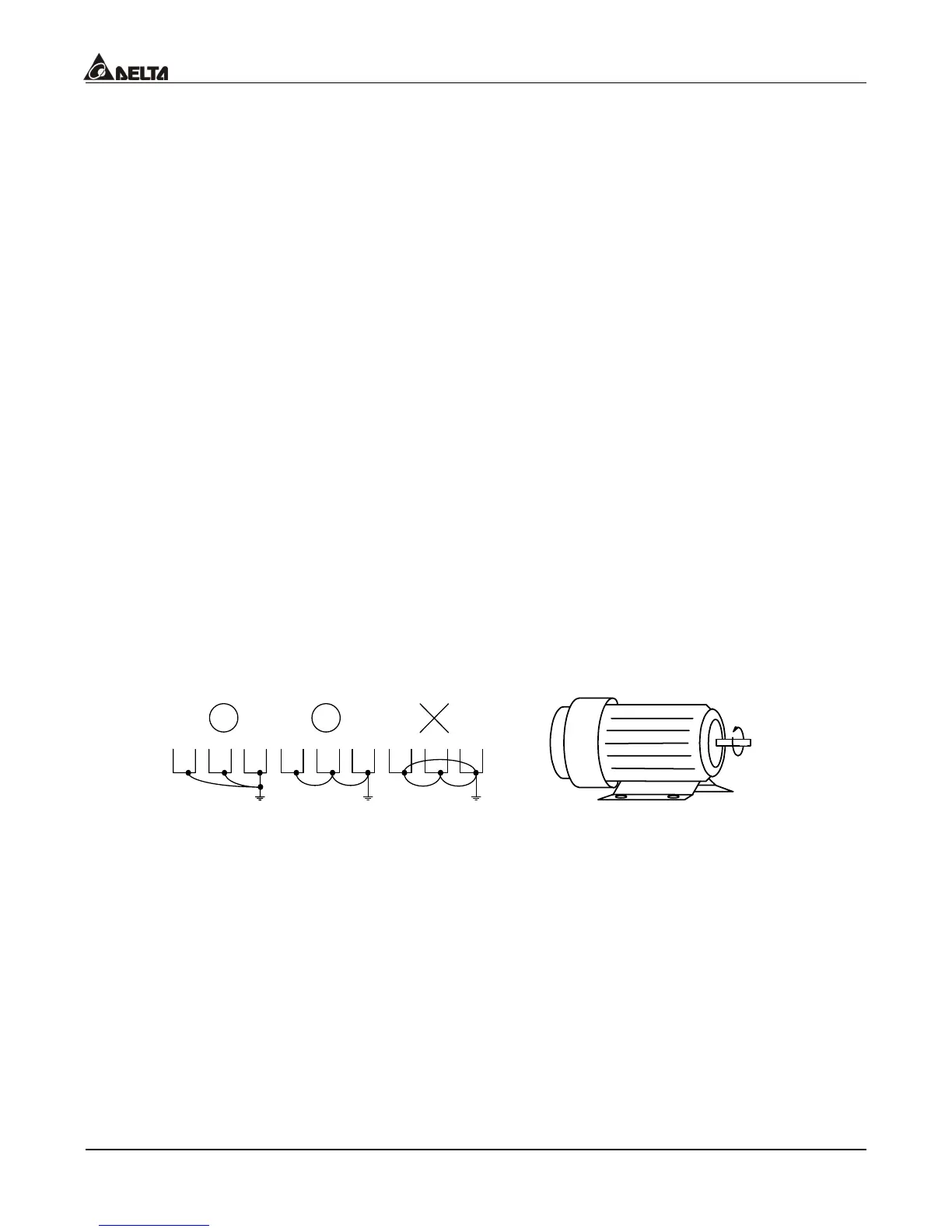
8. When several inverters are grounded at the same time, be sure not to make it into a
ground circuit. Please refer to the following diagram:
FWD RUN
9. If the output terminals U/T1, V/T2 and W/T3 of the inverter are connecting relatively to
the U, V, and W terminals of the motor, the FWD indicator located on the digital control
panel of the inverter will be lit, and that means the inverter is running forward, and the
rotation direction of the motor will be shown as the right hand side diagram above; if the
REV indicator is lit, it means that the inverter is running in reverse direction, and the
rotation direction will be of the opposite direction compared with the above diagram. If
users are not sure of whether the connection between output terminals U/T1, V/T2 and
W/T3 of the inverter is of one-to-one connection with U, V, and W terminals of the motor,
simply swap either two wires among the U, V, and W terminals of the motor for
correction if the inverter is running forward while the motor is running at reverse
direction.

 Loading...