8
VFD-V Series
DELTA ELECTRONICS, INC. ALL RIGHTS RESERVED
8-1
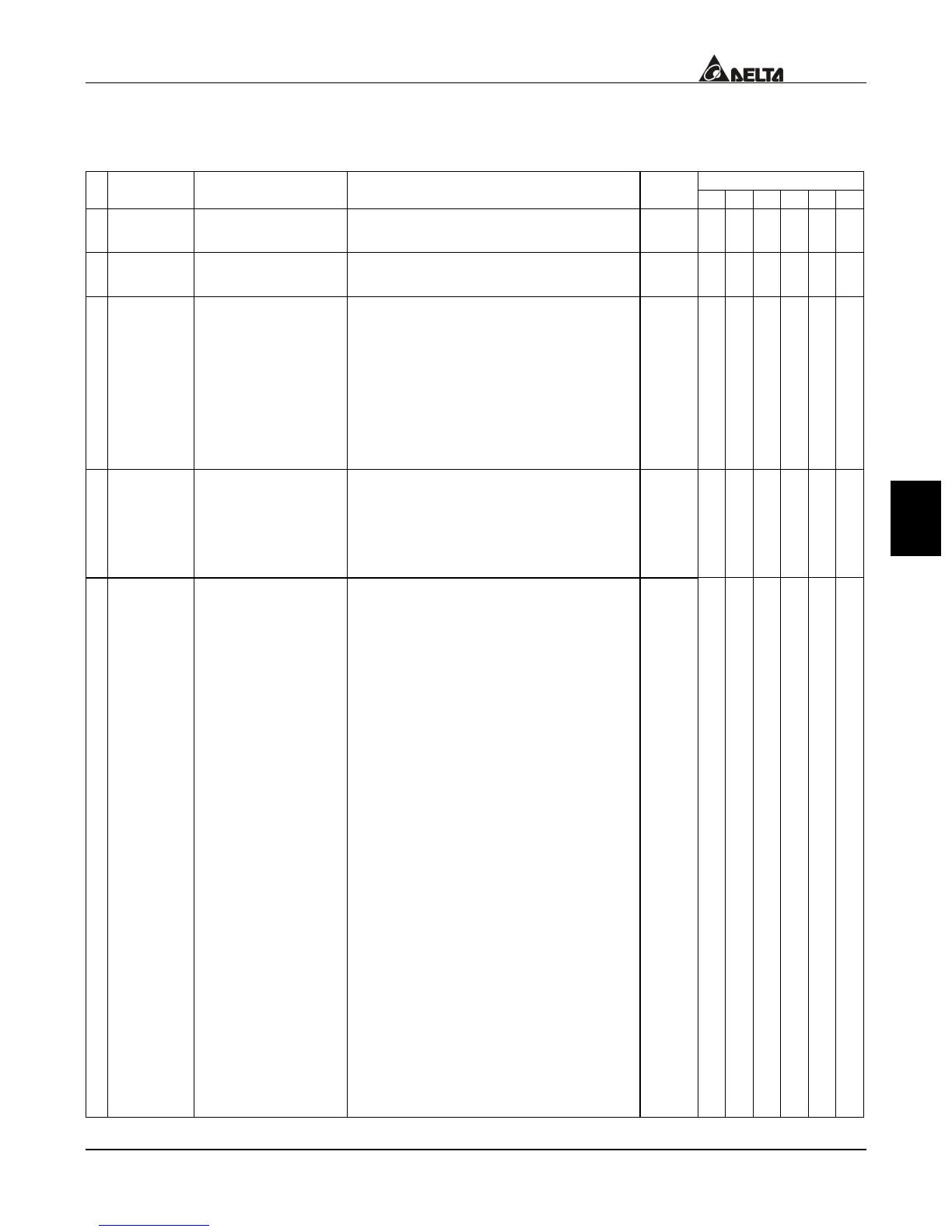
CHAPTER 8 PARAMETER SUMMARY
Group 0: System Parameter
Control Mode
Parameters Functions Settings
Factory
Setting
VF VG SV SG T TG
00-00 Identity Code Based on the model type
Read
Only
{ { { { { {
00-01
Rated Current
Display
Based on the model type
Read
Only
{ { { { { {
00-02 Parameter Reset
10: Parameter reset (for 60Hz
input)
9: Parameter reset (for 50Hz input)
bit 0=1: Parameters are read only
bit 1=1: Disable Frequency and
Torque Command
changes.
bit 2=1: Keypad disable
0
{ { { { { {
a
00-03
Star-up Display of
the Drive
0: F (Master frequency command)
1: H (Output frequency)
2: U (multi-function display of
00-04)
3: Output current
0
{ { { { { {
a
00-04
Definitions of the
Multi-Function
Display
0: output voltage
1: DC-BUS voltage
2: voltage command
3: multi-step speed
4: Speed command for the
Process Control Operation step
5: Time remaining for the Process
Control Operation step
6: Remaining number of times for
the “restart after fault” feature
7: counter value
8: torque loading
9: power factor ±1.000
10: Power factor angle (0~180
degrees)
11: Output power (Kw)
12: Output power (Kva)
13: Motor speed (rpm)
14: IGBT module temperature
15: Braking resistor temperature
16: Digital terminal input status
17: PID output command
18: PID feedback value
19: the q axis voltage (V/F and
vector)
0
{ { { { { {

 Loading...