8
VFD-V Series
DELTA ELECTRONICS, INC. ALL RIGHTS RESERVED
8-13
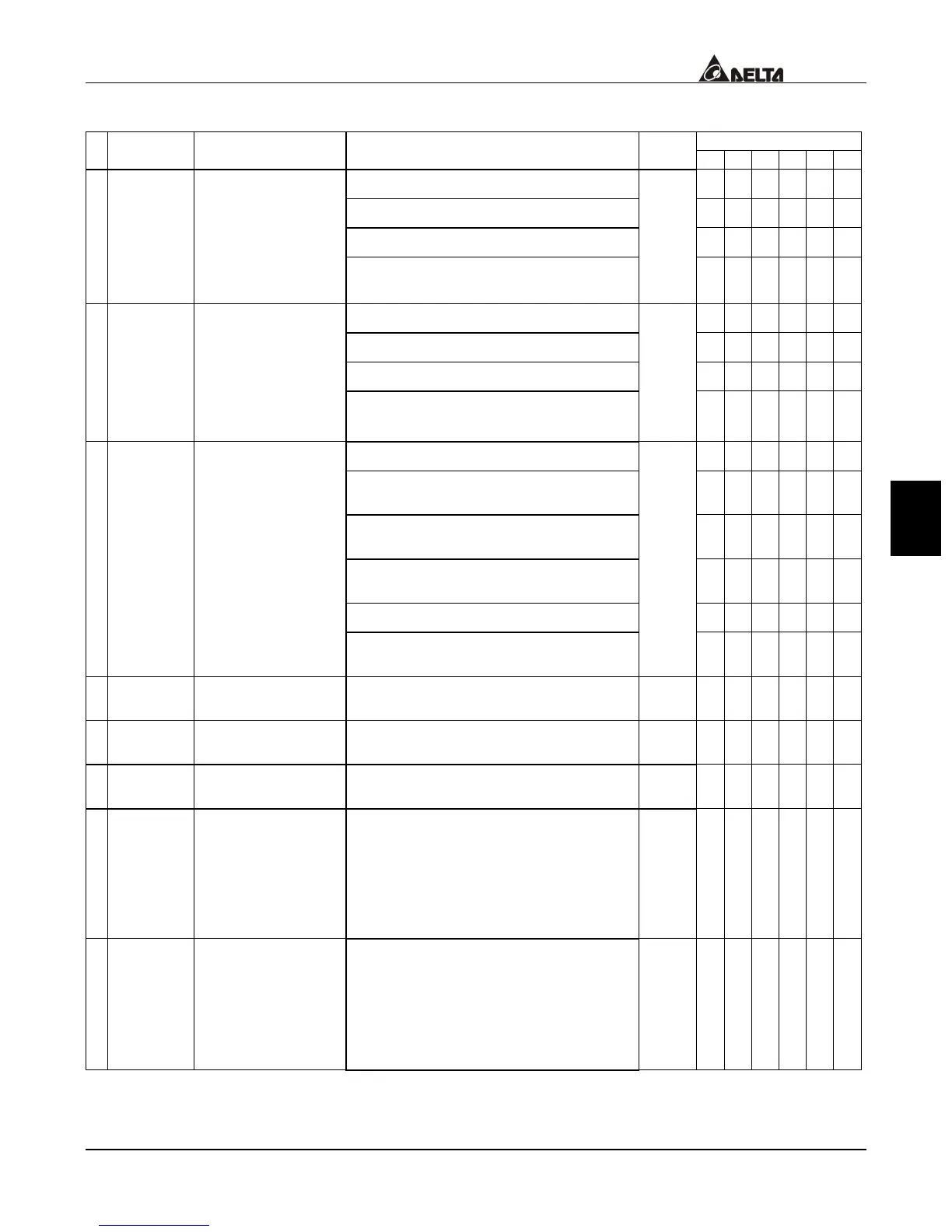
Group 3: Analog Output/Input Parameter
Control Mode
Parameters Functions Settings
Factory
Setting
VF VG SV SG T TG
0: no functions
{ { { { { {
1: frequency/torque command
{ { { { { {
2: torque limitations
° ° { { { {
a
03-00
Analog Input 1
(AVI)
3: acceleration/deceleration time
gain
1
{ { { { ° °
4: upper bound frequency
{ { { { ° °
5: over-torque current level
{ { { { { {
6: torque compensation gain
{ { ° ° ° °
a
03-01
Analog Input 2
(ACI)
7: over-current stall prevention
level during operation
0
{ { { { ° °
8: torque compensation(Vector)
° ° { { { {
9: AVI auxiliary frequency
(multiplication by the ratio of AVI)
{ { { { { {
10: ACI auxiliary frequency
(multiplication by the ratio of ACI)
{ { { { { {
11: AUI auxiliary frequency
(multiplication by the ratio of AUI)
{ { { { { {
12: PID offset
{ { { { { {
a
03-02
Analog Input 3
(AUI)
13: Auxiliary frequency of master
frequency
0
{ { { { { {
a
03-03
(AVI) Analog
Input Bias 1
-10.00~10.00V 0.00
{ { { { { {
a
03-04
(ACI) Analog
Input Bias 2
0.00~20.00mA 4.00
{ { { { { {
a
03-05
(AUI) Analog
Input Bias 3
-10.00~10.00V 0.00
{ { { { { {
a
03-06
(AVI)
Positive/Negative
Bias Mode
0: zero bias
1: value lower than bias = bias
2: value greater than bias = bias
3: the absolute value of the bias
voltage while serving as the
center
0
{ { { { { {
a
03-07
(ACI)
Positive/Negative
Bias Mode
0: zero bias
1: value lower than bias = bias
2: value greater than bias = bias
3: the absolute value of the bias
voltage while serving as the
center
1
{ { { { { {

 Loading...