5
VFD-V Series
DELTA ELECTRONICS, INC. ALL RIGHTS RESERVED
5-75
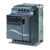
Phase B is a forward run pulse, then phase A is High.
Phase A is a reverse run pulse, then phase B is High.
FWD REV
5
A
B
Phase A leads in a forward run command and phase B leads in a
reverse run command. (level trigger)
FWD REV
6
A
B
Phase B leads in a forward run command and phase A leads in a
reverse run command. (level trigger)
FWD REV
7
A
B
This parameter sets the type of feedback received from the encoder.
The direction is determined as follows:
Forward = motor shaft is turning counter clockwise as viewed from the motors shaft end.
Reverse = motor shaft is turning clockwise as viewed from the motors shaft end.
10-02 PG Feedback Fault Treatment
a
Factory setting 0
Settings 0 warn and keep operating
1 warn and RAMP to stop
2 warn and COAST to stop
10-03 PG Feedback Fault Detection Time
a
Factory setting 0.10
Settings 0.00~10.00 sec
This parameter sets the amount of time to the PG feedback signal may be in error.
The feedback signal is in error if it outside the Slip Range (Pr.10-05) or if is over the Stall
Level (Pr.10-06). Once either of the errors are met, the drive will begin to accumulate
time. If the feedback signal continues to be in error at the end of the Detection Time
period(Pr.10-03) the drive will display a PGerr.
10-04 PG Feedback Filter Time
a
Factory setting 0.003
Settings 0.001~1.000 sec

 Loading...