VFD-V Series
DELTA ELECTRONICS, INC. ALL RIGHTS RESERVED
3-6
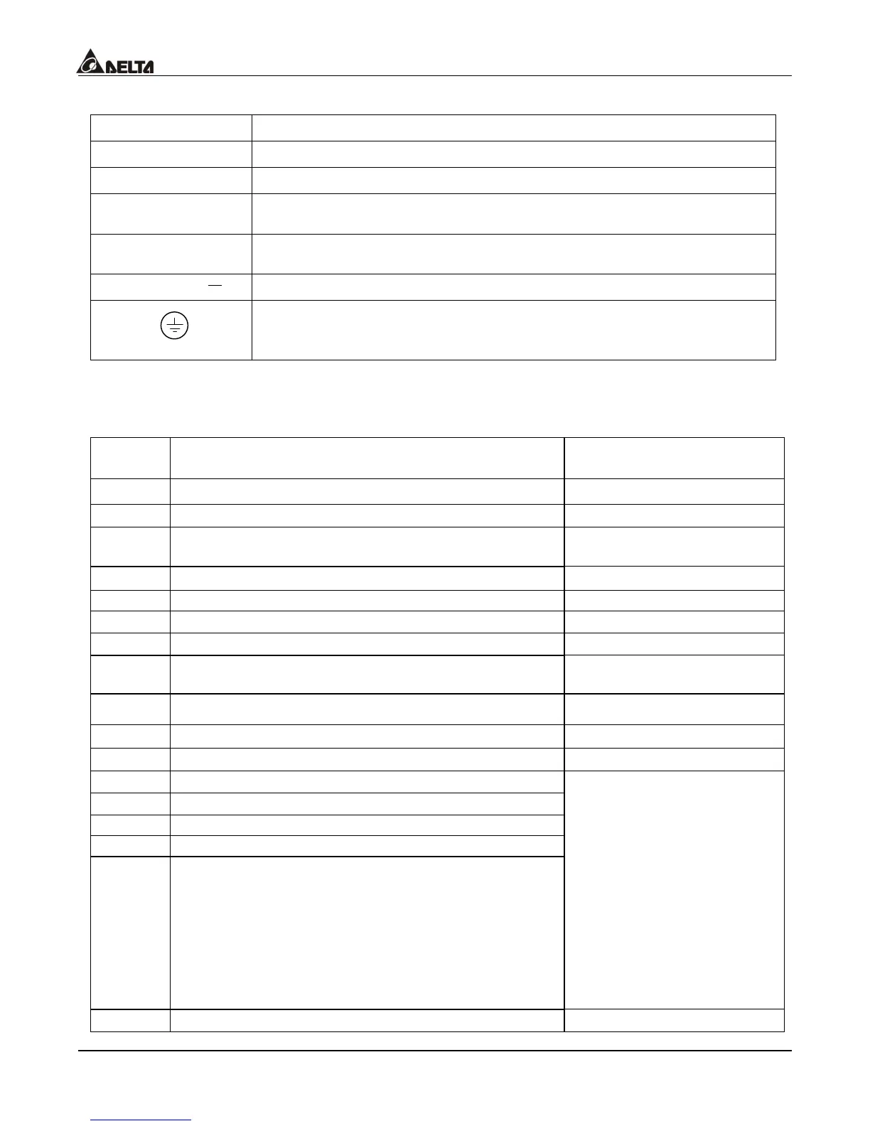
3.3 Main Circuit Terminal Explanations
Terminal Symbol Content Explanation
R/L1, S/L2, T/L3 Input terminals for business-used power supply
U/T1, V/T2, W/T3 Output terminals for the AC motor drivers (at the side of the motor)
+1~+2/B1
Power-improved continuing terminals of the DC reactor; disconnect
the short-circuit piece when the device is installed
+2/B1~B2
Connecting terminals of the braking resistor; purchase and install
these devices according to the selection chart
+2/B1~ Continuing terminals of the braking module (the VFDB series)
Ground terminals, please have these terminals grounded following
the third-type grounding of 230V series and the special grounding of
460V series within the electrician regulations
3.4 Control Terminal Explanations
Terminal
Symbol
Explanation on the Terminal Function Factory Setting
FWD FWD RUN-STOP command
REV REV RUN-STOP command
MI1 Multi-function input selection 1 (3-wire
STOP-designated terminal)
Multi-step 1 command
MI2 Multi-function input selection 2 Multi-step 2 command
MI3 Multi-function input selection 3 Multi-step 3 command
MI4 Multi-function input selection 4 Multi-step 4 command
MI5 Multi-function input selection 5 Abnormal reset command
MI6 Multi-function input selection 6 (TRG-designated
terminal
EF
DFM Digital frequency signal output
1
:
1
+24V Digital control signal – the common end +24V 20mA
DCM Digital control signal – the common end
RA Multi-function relay output contact (NO a)
RB Multi-function relay output contact (NC b)
RC Multi-function relay output contact
MRA Multi-function relay output contact (NO a)
MRC Multi-function relay output contact – the common
end
Resistive Load
5A(N.O.)/3A(N.C.) 240VAC
5A(N.O.)/3A(N.C.) 24VDC
Inductive Load
1.5A(N.O.)/0.5A(N.C.)
240VAC
1.5A(N.O.)/0.5A(N.C.)
24VDC
Refer to Pr.02-11 to
Pr.02-12
MO1 Multi-function output terminal 1 (photo coupler) Instruction during operation

 Loading...