VFD-V Series
DELTA ELECTRONICS, INC. ALL RIGHTS RESERVED
3-2
3.1 Basic Wiring Diagram
For wiring of the inverter, it is divided into the main circuit and the control circuit. Users
could open the case cover, and could inspect the main circuit terminal and the control circuit
terminal; users connect the circuit in compliance with the following wiring method.
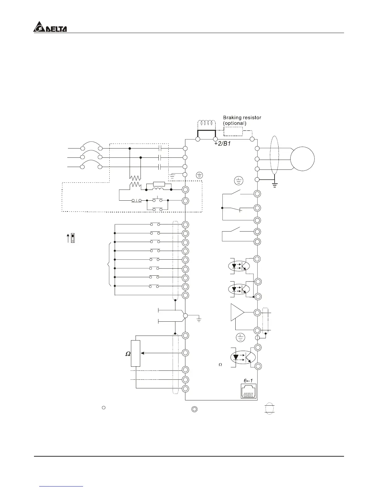
The following diagram is the standard wiring diagram for the VFD-V inverter.
Wiring Diagram 1
10HP(7.5kW) and below
AVI
ACI
AUI
ACM
B2
4~20mA
-10~+10V
+10V
5K
3
2
1
Jumper
Power supply
+10V 20mA
Master Frequency
0 to 10V 47K
Analog Signal Common
DC choke
(optional)
Main circuit (power) terminals
Control circuit terminals
Shielded leads & Cable
FWD
REV
MI1
MI2
MI3
MI4
MI6
MI5
DCM
+24V
Sw1
Sink
Source
Factory Default:
SINK Mode
FWD/STOP
REV/STOP
Multi-step 1
Multi-step 2
Multi-step 3
Multi-step 4
Digital Signal Common
Factory
default
* Don input voltage directly
to the above signals.
Please refer to wiring
of SINK mode and
SOURCE mode.
R/L1
S/L2
T/L3
Fuse/NFB(None Fuse Breaker)
SA
OFF
ON
MC
MC
RB
RC
+1
Recommended Circuit
when power supply
is turned OFF by a
fault output
R/L1
S/L2
T/L3
E
Multi-function Analog Output
Te r m i n a l
Factory default: Output
Frequency 0~ 10VDC/2mA
U/T1
V/T2
W/T3
IM
3~
MO1
MO2
AFM
ACM
RA
RB
RC
RS-485
Motor
Factory default:
Frequency-Achieving Indication
Factory default:
Driver-Ready Indication
Analog Signal common
Serial interface
1: +EV 2: GND
5:NC
6: NC
3: SG-
4: SG+
DFM
DCM
Digital Frequency Output
Te r m i n a l
Factory default: 1:1
Duty=50% 10VDC
Digital Signal Common
E
E
Please refer to ontrol
Terminal Explanation?
Multi-step 5
Multi-step 6
Shield terminal
MRA
MRC
Multi-function Photocoupler
Output 48VDC 50mA
Factory setting:
Operation Indication
MCM
Photocoupler Common
Output Terminal

 Loading...