5
VFD-V Series
DELTA ELECTRONICS, INC. ALL RIGHTS RESERVED
5-27
Desired Counter Value
Attained output
Preset Counter Value
Attained output
0.5ms
Display
(Pr.00-04=07)
TRG
Counter Trigger
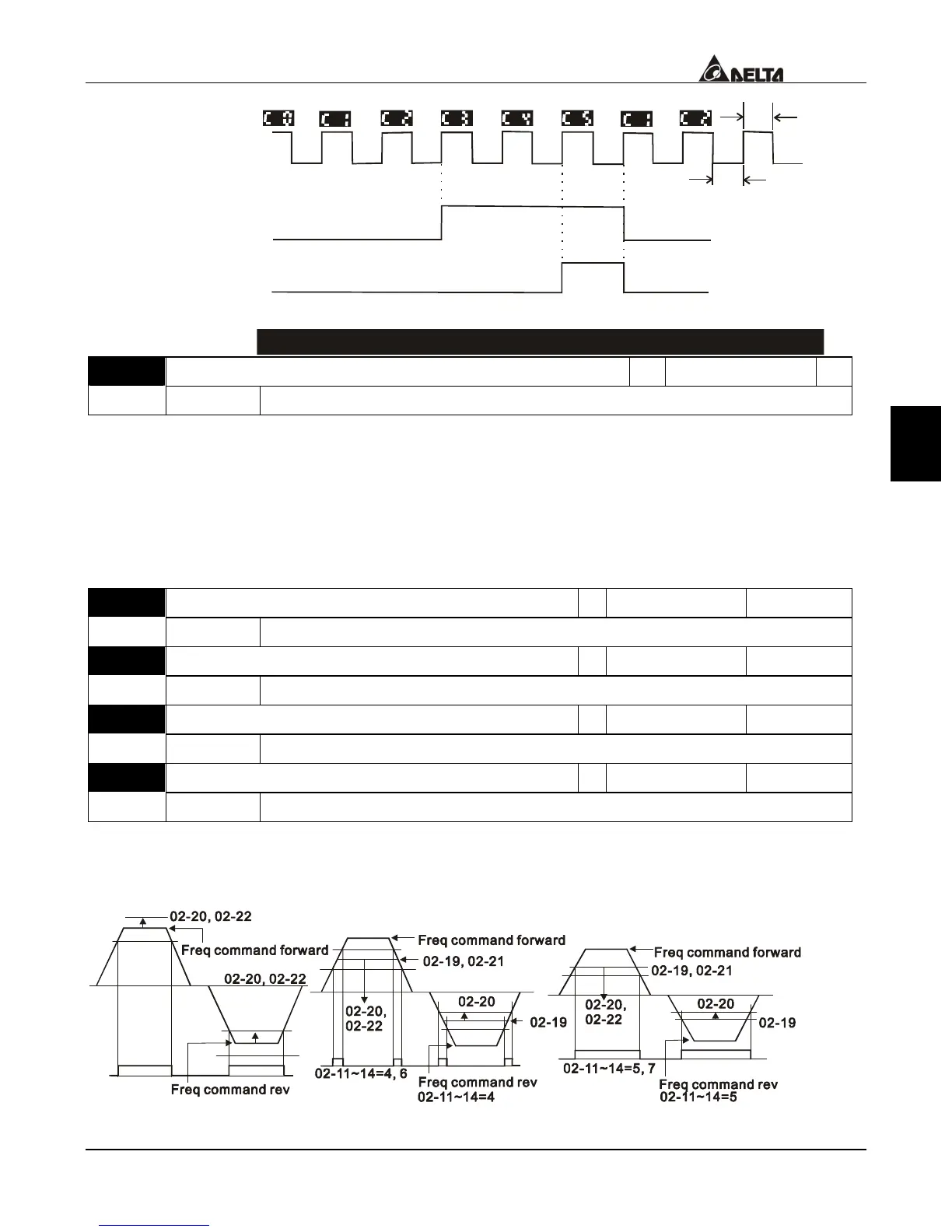
02-12=22
02-16=3
02-13=21
02-15=5
0.5ms
Trigger signal width
(Output signal)
Multi-function output terminal
Pr. 02-10~02-13
Diagram of the External Counter Terminal and the Arrival of the Counter Value
02-18 Digital Output Gain
a
Factory setting 1
Settings 1~40
This parameter determines the signals of the drive’s digital output terminal (DFM-DCM)
and of the digital frequency output (pulse, work period = 50%). Output pulse per
second = output frequency × (Pr. 02-17)。
Setting of the multiple has a lot to do with the carrier frequency; the carrier frequency has
to be greater than “2 x maximum operation frequency x multiplying rate”.
02-19 Pre-set Arrival Frequency 1
a
Factory setting 60.00/50.00
Settings 0.00~400.00Hz
02-20 Pre-set Arrival Frequency 1 Width
a
Factory setting 2.00
Settings 0.00~400.00Hz
02-21 Pre-set Arrival Frequency 2
a
Factory setting 60.00/50.00
Settings 0.00~400.00Hz
02-22 Pre-set Arrival Frequency 2 Width
a
Factory setting 2.00
Settings 0.00~400.00Hz
Once the drive’s output speed (frequency) achieves the arbitrary designated (speed)
frequency, and that if the corresponding multi-function output terminal is set as 2~7 or
24~27 (Pr. 02-10~02-14), then the multi-function output terminal contact will be “closed”.

 Loading...