5
VFD-V Series
DELTA ELECTRONICS, INC. ALL RIGHTS RESERVED
5-3
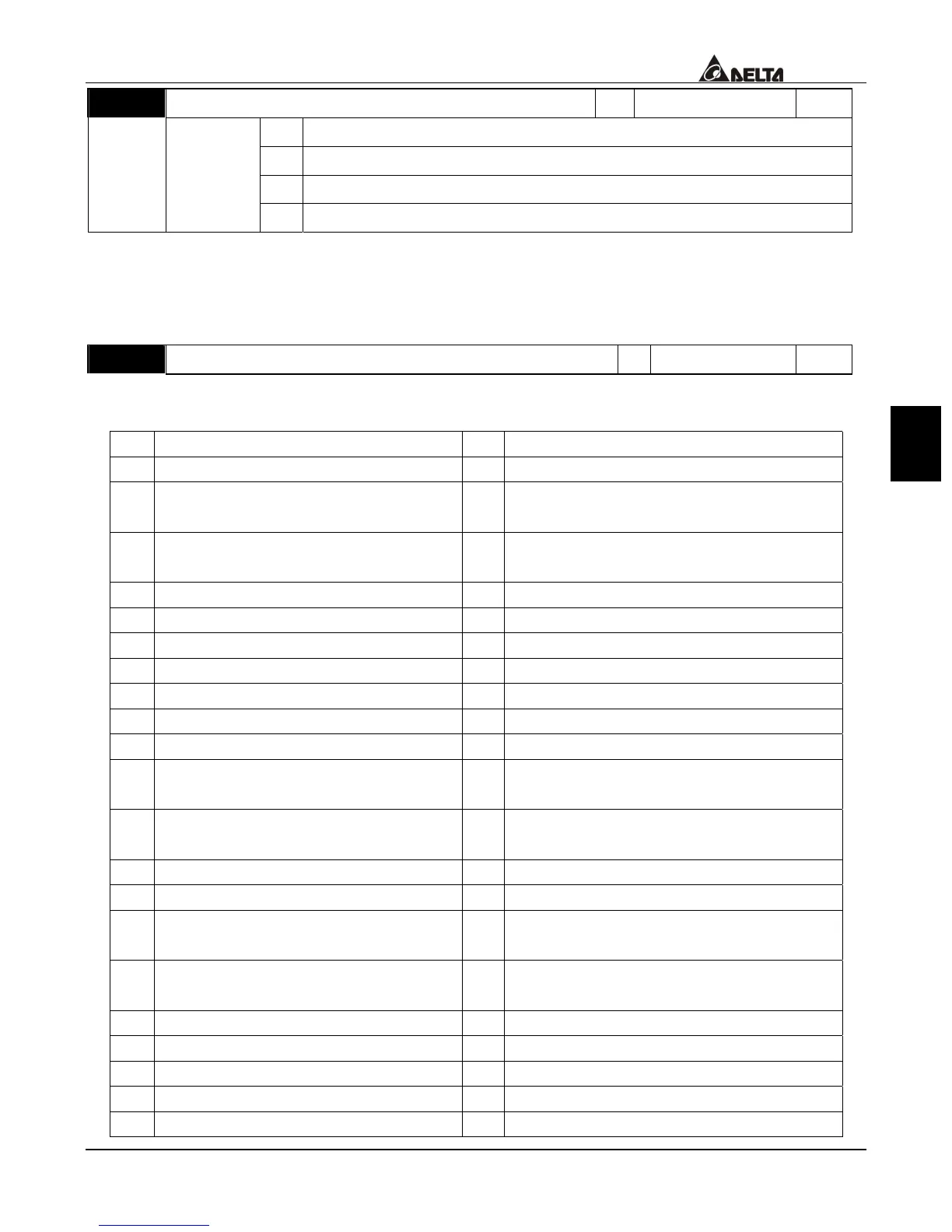
00-03 Start-up Display of the Drive
a
Factory setting 0
Settings 0 F (Master frequency command)
1 H (Output frequency)
2 U (multi-function display of Pr. 00-04)
3 Output current
This parameter allows the start-up display to be customized. The display may still be
changed, but during each power on, the display will default to the setting in this
parameter.
00-04 Definitions of the Multi-Function Display
a
Factory setting 0
Settings
0 output voltage 1 DC-BUS voltage
2 voltage command 3 multi-step speed
4
Speed command for the Process
Control Operation step
5
Time remaining for the Process Control
Operation step
6
Remaining number of times for the
“restart after fault” feature
7 counter value
8 torque loading 9 power factor ±1.000
10 Power factor angle (0~180 degrees) 11 Output power (Kw)
12 Output power (Kva) 13 Motor speed (rpm)
14 IGBT module temperature 15 Braking resistor temperature
16 Digital terminal input status 17 PID output command
18 PID feedback value 19 the q axis voltage (V/F and vector)
20 the d axis voltage (Vector only) 21 Magnetic flux
22 Overload accumulated time 23
Electronic thermal relay accumulated
time
24
Execution time of the multi-step
speed
25 quiescence stage
26 over-torque accumulated time 27 DC braking time
28 Compensated voltage 29 Slip compensation frequency
30
Running number of Encoder
(Channel 1)
31 PG position (position control)
32
Remaining pulses to reach position
control (home position)
33 DC voltage upon a fault
34 The output AC voltage upon a fault 35 The output frequency upon a fault
36 The current value upon a fault 37 the frequency command upon a fault
38 day (power-up time) 39 hour, minute
40 The upper bound frequency value 41 Over-torque level
42 Stall level limitation 43 Torque compensation gain

 Loading...