XBee® Wi-Fi RF Modules
© 2013 Digi International, Inc. 14
SPI
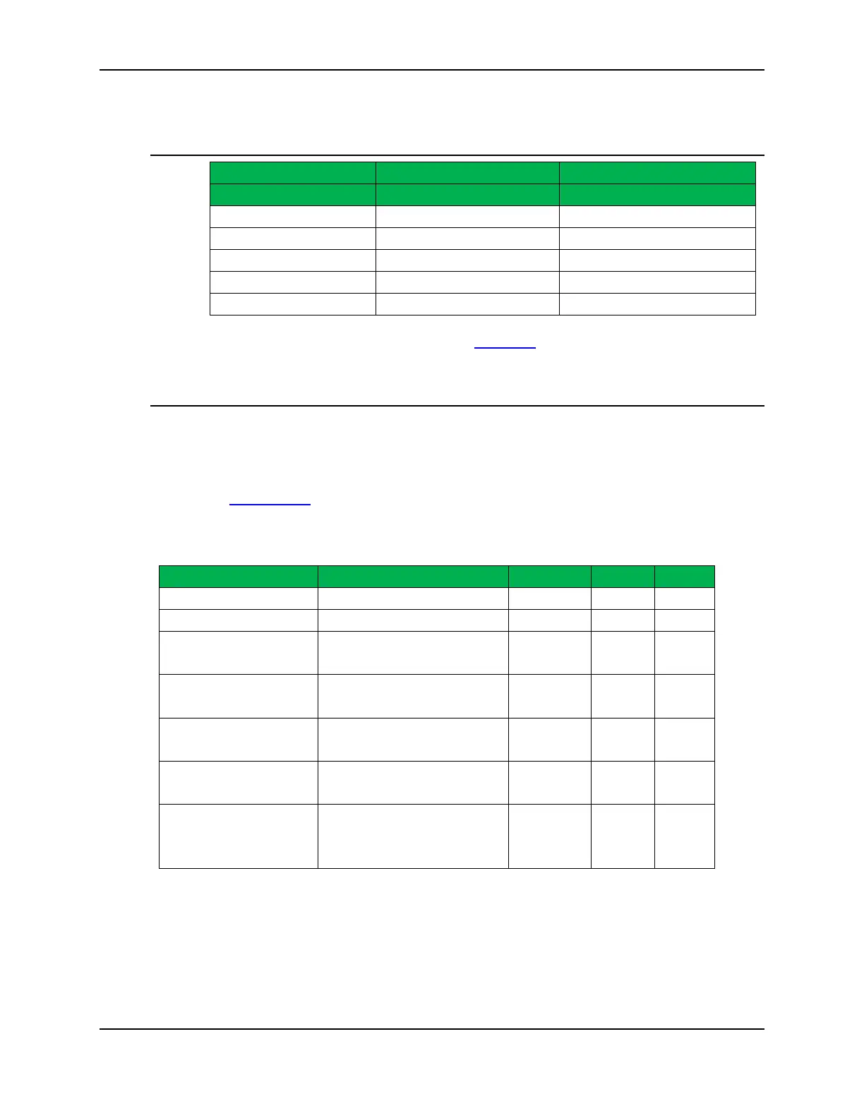
Specification XBee Wi-Fi Through-hole XBee Wi-Fi Surface Mount
SPI Pins Module Pin Number Module Pin Number
DIO2/SPI_SCLK 18 14
DIO3/SPI_nSSEL 17 15
DIO4/SPI_MOSI 11 16
DIO12/SPI_MISO 4 17
DIO1/SPI_nATTN 19 12
For more information on SPI operation see the
SPI section in chapter 2.
GPIO Specifications
The XBee Wi-Fi modules have 14 (Through-hole version) and 20 (Surface mount version)
GPIO (General Purpose Input Output) ports available. Those available will depend on
the module configuration as some GPIO’s are consumed by serial communication, etc.
See
GPIO section for more information on configuring and using GPIO ports
Electrical Specification for GPIO pads
Input Low Voltage
0.3VDD V
Input High Voltage
Output high Voltage relative to
VDD
Sourcing 2 mA, VDD=3.3 V 85
%
Output low voltage relative to
VDD
Sinking 2 mA, VDD=3.3 V
15 %
Output fall time
2 mA drive strength and load
capacitance CL=350-600pF.
I/O pin hysteresis (VIOTHR+ -
VIOTHR-)
VDD = 3.14 to 3.46 V 0.1VDD
V
Pulse width of pulses to be
removed by the glitch
suppression filter

 Loading...


