XBee® Wi-Fi RF Modules
© 2013 Digi International, Inc. 29
Serial Buffers
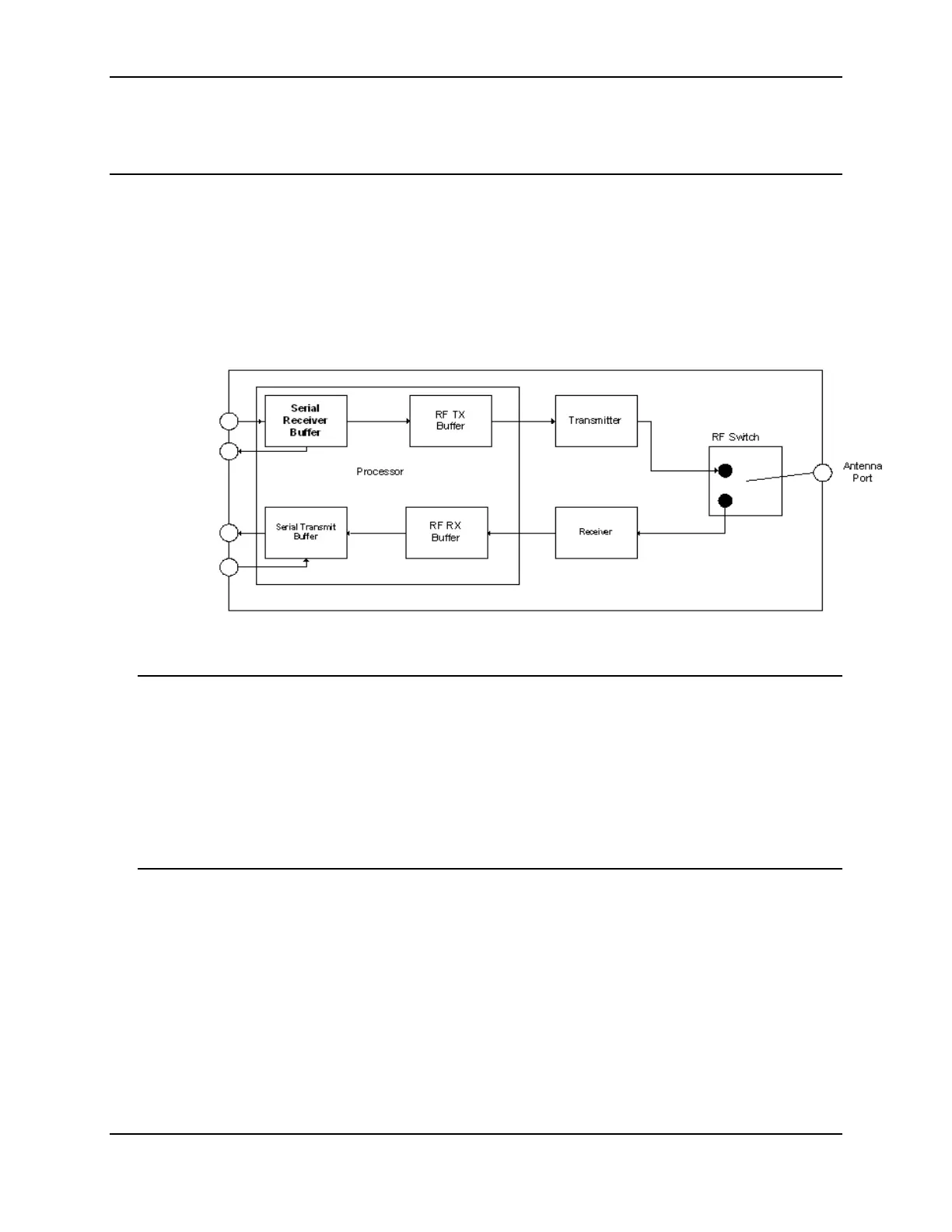
The XBee modules maintain buffers to collect received serial and RF data, which is
illustrated in the figure below. The serial receive buffer collects incoming serial
characters and holds them until they can be processed. The serial transmit buffer
collects data that is received via the RF link that will be transmitted out the UART or SPI
port.
Internal Data Flow Diagram
Serial Receive Buffer
When serial data enters the RF module through the DIN Pin (or the MOSI pin), the data
is stored in the serial receive buffer until it can be processed. Under certain conditions,
the module may not be able to process data in the serial receive buffer immediately. If
large amounts of serial data are sent to the module such that the serial receive buffer
would overflow, then the new data will be discarded. If the UART is in use, this can be
avoided by the host side honoring CTS flow control.
Serial Transmit Buffer
When RF data is received, the data is moved into the serial transmit buffer and sent out
the UART or SPI port. If the serial transmit buffer becomes full and system buffers are
also full, then the entire RF data packet is dropped. Whenever data is received faster
than it can be processed and transmitted out the serial port, there is a potential of
dropping data, even in TCP mode.
DIN or MOSI
CTS
DOUT or MISO
RTS

 Loading...


