XBee® Wi-Fi RF Modules
© 2013 Digi International, Inc. 52
6. Advanced Application Features
XBee Analog and Digital I/O Lines
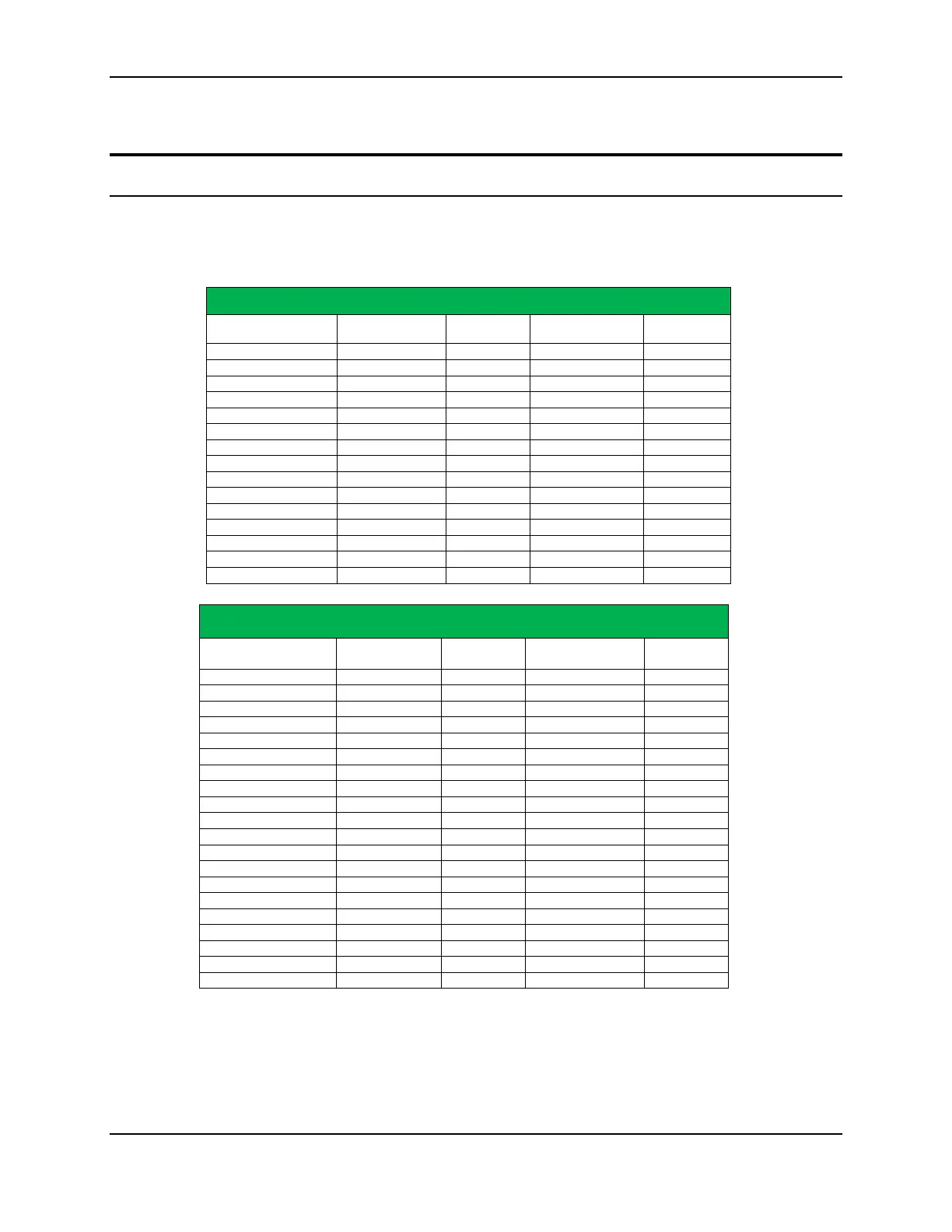
XBee Wi-Fi firmware supports a number of analog and digital I/O pins that are
configured through software commands. Analog and digital I/O lines can be set or
queried. The following tables list the configurable I/O pins and the corresponding
configuration commands.
Through Hole Module
Pin name(s) Module pin AT cmd Command Range Default Value
DIO0/AD0 20 D0 0,2-5 0
DIO1/AD1/ SPI_nATTN 19 D1 0-5 0
DIO2/AD2/SPI_CLK 18 D2 0-5 0
DIO4/SPI_MOSI 11 D4 0-1,3-5 0
DIO5/ASSOCIATE 15 D5 0-1,3-5 1
DIO6/nRTS 16 D6 0-1,3-5 0
DIO8/nDTR/SLEEP_RQ 9 D8 0-1,3-5 1
DIO9/On_nSLEEP 13 D9 0-1,3-5 1
DIO10/PWM0 6 P0 0,2-5 0
DIO12/SPI_MISO 4 P2 0-1,3-5 0
DIO13/DOUT 2 P3 0-1 1
DIO14/DIN/nCONFIG 3 P4 0-1 1
SMT Module
Pin name(s) Module pin AT cmd Command Range
Default
DIO0/AD0 33 D0 0,2-5 0
DIO1/AD1 32 D1 0,2-5 0
DIO2/AD2 31 D2 0,2-5 0
DIO4 24 D4 0,3-5 0
DIO5/ASSOCIATE 28 D5 0-1,3-5 1
DIO6/nRTS 29 D6 0-1,3-5 0
DIO8/nDTR/SLEEP_RQ 10 D8 0-1,3-5 1
DIO9/On_nSLEEP 26 D9 0-1,3-5 1
DIO10/PWM0 7 P0 0,2-5 0
DIO11/PWM1 8 P1 0,2-5 0
DIO12 5 P2 0,3-5 0
DIO13/DOUT 3 P3 0-1 1
DIO15/SPI_MISO 17 P5 0-1,4-5 1
DIO16/SPI_MOSI 16 P6 0-1,4-5 1
DIO17/SPI_nSSEL 15 P7 0-1,4-5 1
DIO19/SPI_nATTN 12 P9 0-1,4-6 1

 Loading...


