XBee® Wi-Fi RF Modules
© 2013 Digi International, Inc. 53
I/O Configuration
To enable an analog or digital I/O function on one or more XBee module pin(s), the
appropriate configuration command must be issued with the correct parameter. After
issuing the configuration command, changes must be applied on the module for the I/O
settings to take effect. Pull-up/down resistors can be set for each digital input line using
the PR command. The PR value updates the state of all pull-up/down resistors, and the
PD command determines if a pull-up or pull-down is used. See Chapter 8 for information
on these commands.
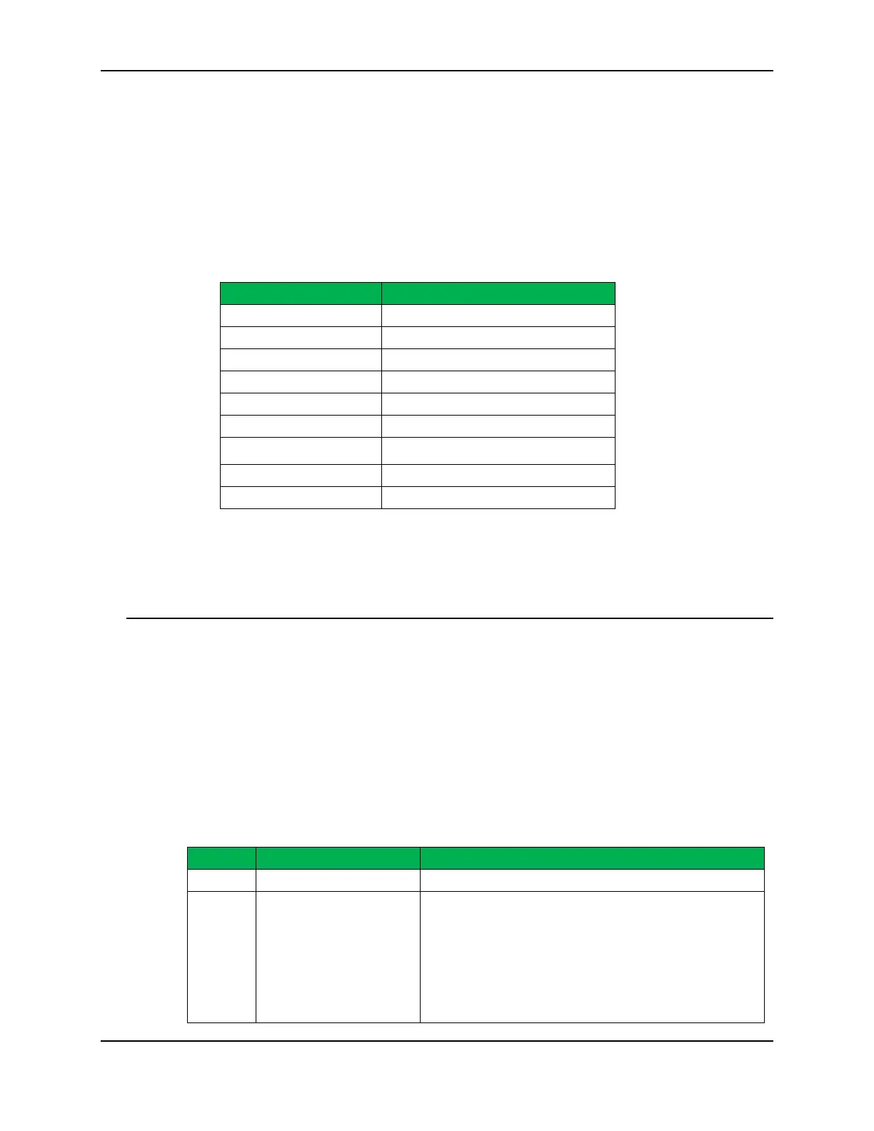
Pin Command Parameter Description
0
Disabled
1
Peripheral control
2
Analog input or PWM output
3
4
Data out default low
5
6
RS485 enable low
7
RS485 enable high
>7
I/O Sampling
The XBee modules have the ability to monitor and sample the analog and digital I/O
lines. I/O samples indicate the current state of I/O lines. These samples may be output
on the local (serial) port, transmitted to a remote Xbee module, or sent to the iDigi
server.
There are three ways to obtain I/O samples, either locally or remotely:
• Queried Sampling
• Periodic Sampling
• Change Detection Sampling.
IO sample data is formatted as shown in the table below
Bytes Name Description
1 Sample Sets
Number of sample sets in the packet. (Always set to 1.)
2 Digital Channel mask
Digital IO line on the module.
• bit 0 = DIO0
• bit 1 = DIO1
• bit 2 = DIO2
• bit 3 = DIO3
• bit 4 = DIO4
• bit 5 = DIO5
• bit 6 = DIO6
•
 Loading...


