XBee® Wi-Fi RF Modules
© 2013 Digi International, Inc. 17
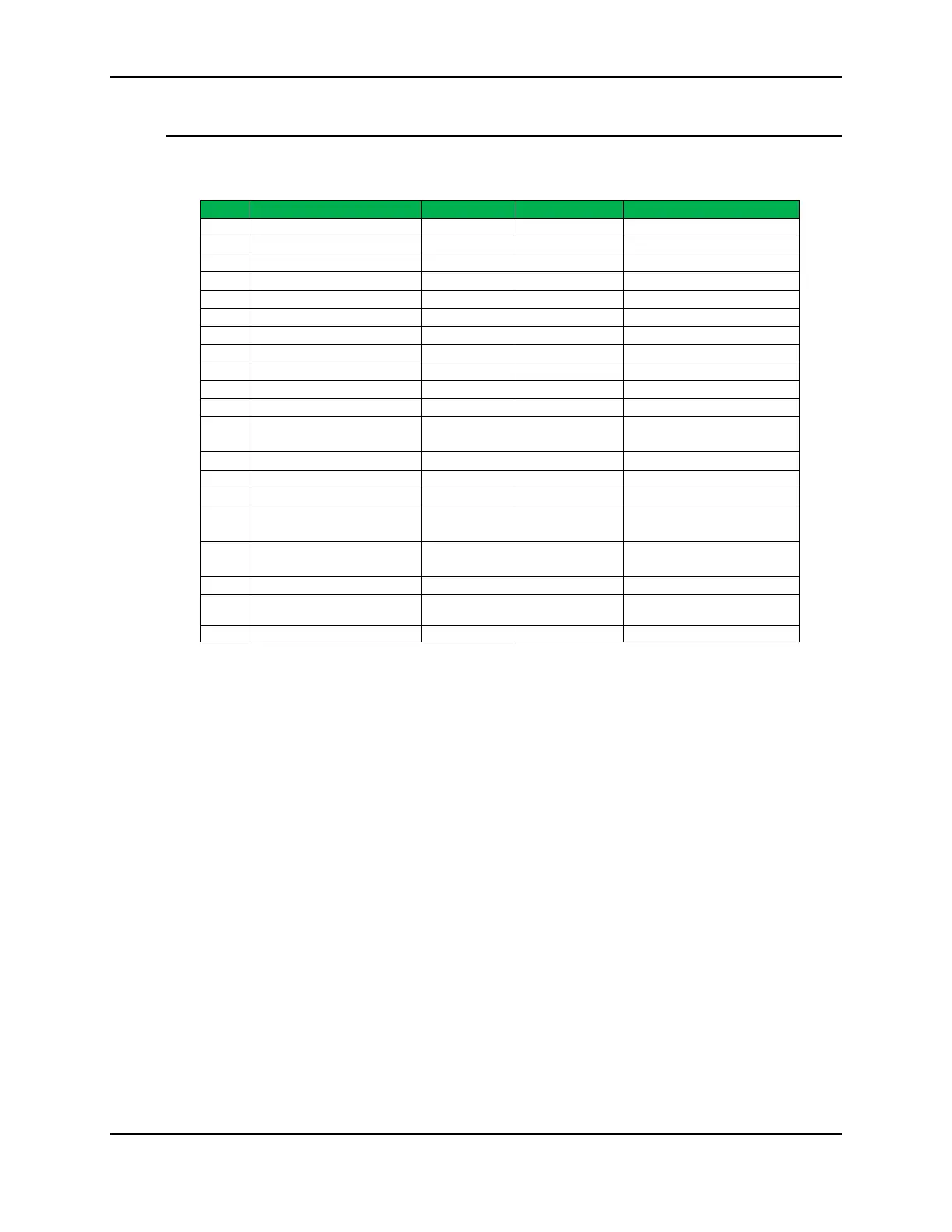
Pin Signals
Pin Assignment for the XBee Wi-Fi Through-hole module
(Low-asserted signals are distinguished with a lower case n before the signal name.)
Pin # Name Direction Default State Description
1 VCC - - Power Supply
2 DIO13/DOUT Both Output UART Data out
3 DIO14/DIN/nCONFIG Both Input UART Data In
4 DIO12/SPI_MISO Both Disabled GPIO/ SPI slave out
5 nRESET Input Input Module Reset
6 DIO10/PWM0 Both Disabled GPIO
7 DIO11/PWM1 Both Disabled GPIO
8 reserved - - Do Not Connect
9 DIO8/nDTR/SLEEP_RQ Both Input Pin Sleep Control line /GPIO
10 GND - - Ground
11 DIO4/SPI_MOSI Both Disabled GPIO/SPI slave In
12 DIO7/nCTS Both Output
Clear-to-Send Flow
Control/GPIO
13 DIO9/ON_nSLEEP Both Output Module Status Indicator/GPIO
14 VREF - - Not connected
15 DIO5/ASSOCIATE Both Output Associate Indicator/GPIO
16 DIO6/nRTS Both Input
Request-to-Send Flow
Control/GPIO
17 DIO3/AD3 /SPI_nSSEL Both Disabled
Analog Input/GPIO/SPI Slave
Select
18 DIO2/AD2 /SPI_CLK Both Disabled Analog Input/GPIO/SPI Clock
19 DIO1/AD1 /SPI_nATTN Both Disabled
Analog Input/GPIO/SPI
Attention
20 DIO0/AD0 Both Disabled Analog Input/GPIO

 Loading...


