XBee® Wi-Fi RF Modules
© 2013 Digi International, Inc. 87
IO Data Sample RX Indicator
Frame Type: 0x8F
When the module receives an IO sample frame from a remote module, it sends the sample out the
UART or SPI using this frame type. Only modules running API mode will be able to receive IO
samples.
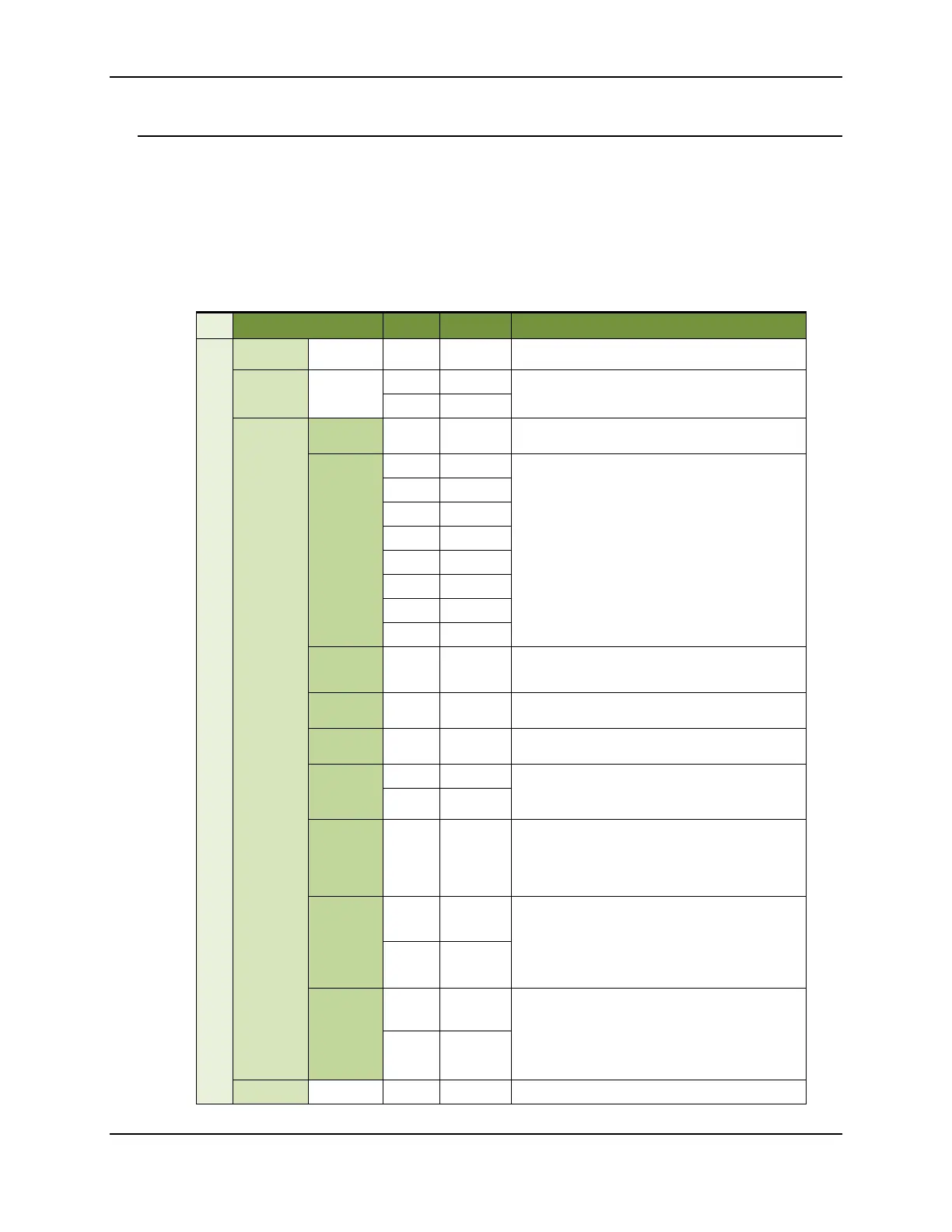
Example: The following is the IO sample response from a radio at IP address 192.168.0.103
reporting one active DIO (DIO8) and one active analog input (AN1).
Frame Fields Offset Example Description
API Packet
Start
Delimiter
0 0x7E
Length
MSB 1 0x00
Number of bytes between the length and the
checksum
LSB 2 0x13
API Frame
Specific
Data
API Frame
Identifier
3 0x8F
64-Bit
Source
Address
4 0x00
Align IP address to low 32-bits of the field. The other
bytes set to 0. IP address is in hex. The example uses
address 192.168.0.103
5 0x00
6 0x00
7 0x00
8 0xC0
9 0xA8
10 0x00
11 0x67
RSSI in
terms of
link margin
12 0x2E
Receive
Options
13 0x00 None currently defined
Number of
samples
14 0x01
Number of sample sets included in the payload.
(Always set to 1)
Digital
Channel
Mask*
MSB 15 0x01
Bitmask field that indicates which digital IO lines on
the remote have sampling enabled (if any). In this
example DIO8 is active.
LSB 16 0x00
Analog
Channel
Mask**
17 0x81
Bitmask field that indicates which analog IO lines on
the remote have sampling enabled (if any). The most
significant bit signals that the Vcc value is included in
the frame. In this example Analog input 1 and Vcc are
Digital
Samples (if
included)
MSB
18
0x00
If the sample set includes any digital IO lines (Digital
Channel Mask > 0), these two bytes contain samples
for all enabled digital IO lines. DIO lines that do not
have sampling enabled return 0. The bits in these 2
bytes map the same as they do in the Digital Channels
Mask field. In this example, DIO8 has value 0.
LSB 19 0x00
Analog
Sample
MSB
20
0x03
If the sample set includes any analog input lines
(Analog Channel Mask > 0), each enabled analog input
returns a 2-byte value indicating the A/D
measurement of that input. Analog samples are
ordered sequentially from DIO0/AD0 to DIO3/AD3, to
the supply voltage.
LSB 21 0xB5
Checksum 22 0x38 0xFF - the 8 bit sum of bytes from offset 3 to this byte.